2TR-FBE BATTERY / CHARGING GENERATOR DISASSEMBLY
PROCEDURE

 27416
1.REMOVE GENERATOR PULLEY CAP
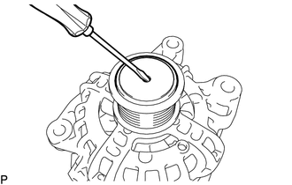
Using a screwdriver, puncture the center of the generator pulley cap and pry it off from the generator pulley set.
- NOTICE:
-
Do not reuse the generator pulley cap.
27403
2.REMOVE GENERATOR PULLEY SET
Secure the generator assembly in a vise between aluminum plates.
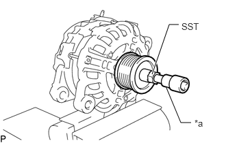
| *a | 8 mm Bi-hexagon Wrench |
Set SST and an 8 mm bi-hexagon wrench to the generator pulley set.
- SST
- 09820-30010
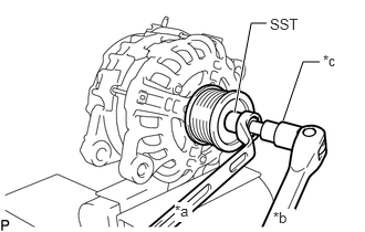
| *a | Hold |
| *b | Turn |
| *c | 8 mm Bi-hexagon Wrench |
While holding SST in place, rotate the 8 mm bi-hexagon wrench clockwise, and remove the generator pulley set.
- NOTICE:
-
Check that the generator drive end frame is secured in the vise tightly.
Remove the generator assembly from the vise.
27039
3.REMOVE REAR GENERATOR END COVER
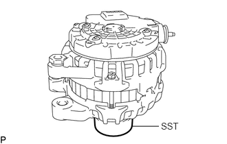
Place the generator assembly on SST.
- SST
- 09630-00014 (09631-00061)
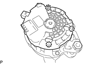
Detach the 3 claws and remove the rear generator end cover from the generator assembly.
27700A
4.REMOVE GENERATOR REGULATOR ASSEMBLY
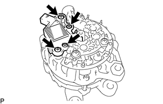
Remove the 4 screws and generator regulator assembly from the rectifier end frame assembly.
27350
5.REMOVE RECTIFIER END FRAME ASSEMBLY
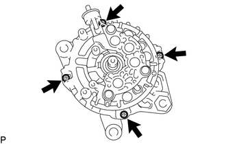
Remove the 4 bolts from the rectifier end frame assembly.
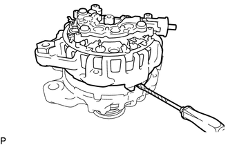
Remove the rectifier end frame assembly from the generator drive end frame.
- HINT:
-
Tape the screwdriver tip before use.
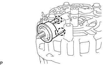
Detach the 2 claws and remove the protective tower from the rectifier end frame.
- HINT:
-
If the protective tower is damaged, replace it.
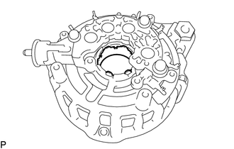
Remove the fitting ring from the rectifier end frame.
- HINT:
-
If the fitting ring is damaged, replace it.
27330
6.REMOVE GENERATOR ROTOR ASSEMBLY
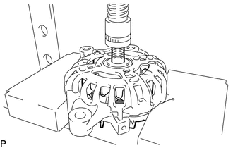
Using a press, press out the generator rotor assembly and remove the generator drive end frame.
- NOTICE:
-
Do not drop the generator rotor assembly.
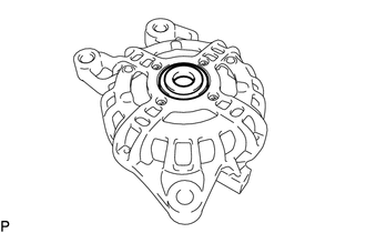
Remove the spacer from the generator drive end frame.
27330A
7.REMOVE GENERATOR ROTOR BEARING
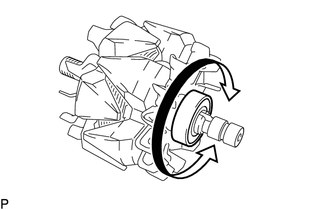
Check that the generator rotor bearing is not rough or worn, and that it rotates smoothly.
If necessary, replace the generator rotor bearing.
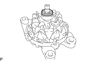
Remove the spinner gate from the generator rotor assembly.
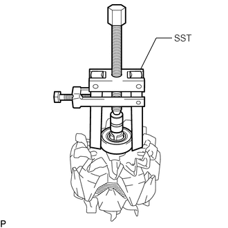
Using SST, remove the generator rotor bearing from the generator rotor assembly.
- SST
- 09286-46011
27404
8.REMOVE GENERATOR BEARING SET
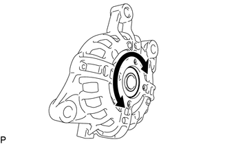

|
Free |
Check that the bearing is not rough or worn, and that it rotates smoothly.
If necessary, replace the generator bearing set.
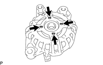
Remove the 4 screws and retainer plate from the generator drive end frame.
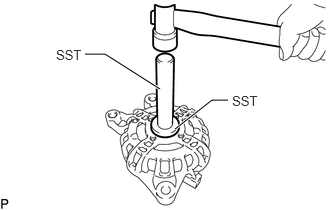
Using SST and a plastic-faced hammer, tap out the generator bearing set from the generator drive end frame.
- SST
- 09950-60010 (09951-00410)
09950-70010 (09951-07100)