2TR-FBE BATTERY / CHARGING GENERATOR REASSEMBLY
PROCEDURE

 27404
1.INSTALL GENERATOR BEARING SET
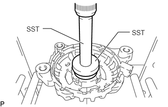
Using SST and a press, press in a new generator bearing set to the generator drive end frame.
- SST
- 09950-60010 (09951-00520)
09950-70010 (09951-07100)
Install the retainer plate to the generator drive end frame with the 4 screws.
- Torque:
- 2.8 N*m (29 kgf*cm, 25 in.*lbf)
27330A
2.INSTALL GENERATOR ROTOR BEARING
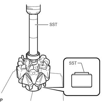
Using a press and SST, install a new generator rotor bearing to the generator rotor assembly.
- SST
- 09285-76010
09630-00014 (09631-00061)
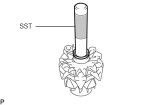
Using SST and a plastic-faced hammer, tap in the spinner gate to the generator rotor assembly.
- SST
- 09285-76010
27330
3.INSTALL GENERATOR ROTOR ASSEMBLY
- NOTICE:
-
Do not drop the generator rotor assembly.
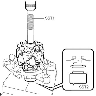
| *1 | Spacer |
Set the spacer, drive end frame, generator rotor assembly and SST1 to SST2 as shown in the illustration.
- SST
- 09285-76010
09630-00014 (09631-00061)
Using SST1, SST2 and a press, slowly press the generator rotor assembly into the generator drive end frame and spacer.
Temporarily install the generator pulley set to the rotor shaft by hand.
27350
4.INSTALL RECTIFIER END FRAME ASSEMBLY
Install a new fitting ring to the rectifier end frame.
Attach the 2 claws and install a new protective tower to the rectifier end frame.
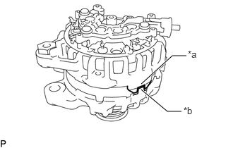
| *a | Keyway |
| *b | Key |
Align the key of the generator drive end frame with the keyway of the generator stator assembly.
Install the generator stator assembly to the generator drive end frame with the 4 bolts.
- Torque:
- 4.3 N*m (44 kgf*cm, 38 in.*lbf)
27700A
5.INSTALL GENERATOR REGULATOR ASSEMBLY
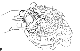
Push in the generator regulator assembly by hand to the rectifier end frame assembly.
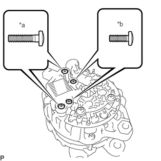
| *a | Screw A |
| *b | Screw B |
Install the generator regulator assembly to the rectifier end frame assembly with the 4 screws.
- Torque:
- for screw A : 2.5 N*m (25 kgf*cm, 22 in.*lbf)
- for screw B : 1.2 N*m (12 kgf*cm, 11 in.*lbf)
27039
6.INSTALL REAR GENERATOR END COVER
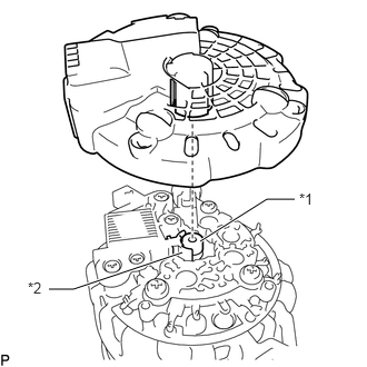
| *1 | Generator Regulator Assembly |
| *2 | Generator Rotor Assembly Shaft |
Attach the 3 claws and install the rear generator end cover to the rectifier end frame assembly.
- HINT:
-
Align the protrusion of the rear generator end cover to the groove between the generator regulator assembly and generator rotor assembly shaft.
27403
7.INSTALL GENERATOR PULLEY SET
Secure the generator assembly in a vise between aluminum plates.
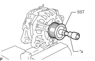
| *a | 8 mm Bi-hexagon Wrench |
Set SST and an 8 mm bi-hexagon wrench as shown in the illustration.
- SST
- 09820-30010
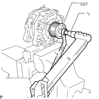
| *a | Hold |
| *b | Turn |
| *c | 8 mm Bi-hexagon Wrench |
While holding SST in place, rotate the 8 mm bi-hexagon wrench counterclockwise, and install the generator pulley set.
- Torque:
- 80 N*m (816 kgf*cm, 59 ft.*lbf)
- NOTICE:
-
Check that the generator drive end frame is secured in the vise tightly.
Remove the generator assembly from the vise.
27416
8.INSTALL GENERATOR PULLEY CAP
Install a new generator pulley cap to the generator pulley set.