Home › Drivetrain › AC60E AUTOMATIC TRANSMISSION / TRANSAXLE › AUTOMATIC TRANSMISSION SYSTEM › from 2016.07
RM33J0E _52 Drivetrain _053789 AC60E AUTOMATIC TRANSMISSION / TRANSAXLE _0275280 AUTOMATIC TRANSMISSION SYSTEM J

AC60E AUTOMATIC TRANSMISSION / TRANSAXLE  AUTOMATIC TRANSMISSION SYSTEM  Pattern Select Switch Power Mode Circuit  


DESCRIPTION

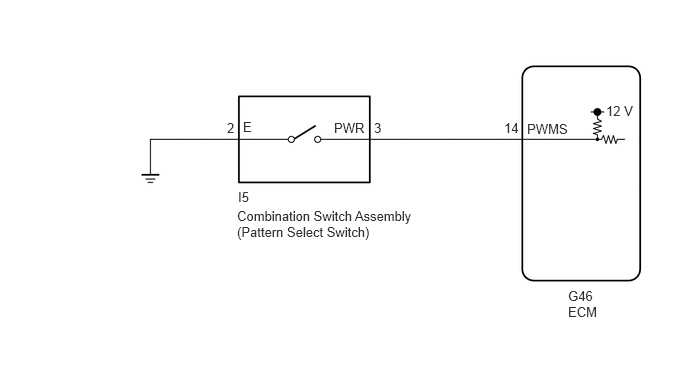
The ECM memory contains the programs for the normal and PWR shift patterns.

By following the programs corresponding to the signals from the combination switch assembly (pattern select switch), park/neutral position switch and other various sensors, the ECM switches the shift solenoid valves on and off, and controls the transmission gear ratio.

WIRING DIAGRAM
C326150E05
6.313,1.073 6.646,1.26 0.333,0.188 10 false 12 V 5.917,3 6.25,3.198 0.333,0.198 10 false G46 5.917,3.167 6.271,3.365 0.354,0.198 10 false ECM 5.25,1.25 5.469,1.448 0.219,0.198 10 false 14 3.896,1.25 4.052,1.448 0.156,0.198 10 false 3 3.479,1.25 3.938,1.448 0.458,0.198 10 false PWR 2.531,1.24 2.688,1.438 0.156,0.198 10 false E 2.365,1.25 2.521,1.448 0.156,0.198 10 false 2 5.49,1.26 6.104,1.458 0.615,0.198 10 false PWMS 2.479,1.969 2.792,2.167 0.313,0.198 10 false I5 2.469,2.167 4.344,2.51 1.875,0.344 10 false Combination Switch Assembly (Pattern Select Switch)

PROCEDURE

1.INSPECT COMBINATION SWITCH ASSEMBLY (PATTERN SELECT SWITCH)
a.
C324163C01
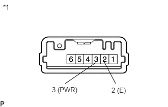
1.333,1.708 1.958,1.281 false 2.365,1.708 2.135,1.271 false 0.063,0.063 0.375,0.26 0.313,0.198 10 false *1 1.063,1.75 1.667,1.948 0.604,0.198 10 false 3 (PWR) 2.281,1.76 2.688,1.948 0.406,0.188 10 false 2 (E)
*1 Combination Switch Assembly (Pattern Select Switch)


Remove the combination switch assembly (pattern select switch).

Click hereDrivetrain>AC60E AUTOMATIC TRANSMISSION / TRANSAXLE>PATTERN SELECT SWITCH>REMOVAL


b.

Measure the resistance according to the value(s) in the table below.

Standard Resistance:
Tester Connection Switch Condition Specified Condition
3 (PWR) - 2 (E) Combination switch (PWR) pushed Below 1 Ω
3 (PWR) - 2 (E) Combination switch (PWR) not pushed 10 kΩ or higher


Result:
Proceed to
OK
NG


OK

2.CHECK HARNESS AND CONNECTOR (COMBINATION SWITCH - BODY GROUND)

NG

REPLACE COMBINATION SWITCH ASSEMBLY (PATTERN SELECT SWITCH)

2.CHECK HARNESS AND CONNECTOR (COMBINATION SWITCH - BODY GROUND)
a.
C323648C03
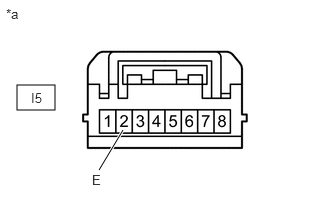
0.177,0.885 0.573,1.146 0.396,0.26 1.031,1.771 1.281,1.354 true 0.958,1.792 1.115,1.99 0.156,0.198 10 false E 0.323,0.938 0.583,1.135 0.26,0.198 10 false I5 0.063,0.063 0.365,0.271 0.302,0.208 10 false *a
*a Front view of wire harness connector
(to Combination Switch Assembly (Pattern Select Switch))


Disconnect the combination switch assembly (pattern select switch) connector.


b.

Measure the resistance according to the value(s) in the table below.

Standard Resistance:
Tester Connection Condition Specified Condition
I5-2 (E) - Body ground Always Below 1 Ω


Result:
Proceed to
OK
NG


OK

3.CHECK HARNESS AND CONNECTOR (COMBINATION SWITCH - ECM)

NG

REPAIR OR REPLACE HARNESS OR CONNECTOR

3.CHECK HARNESS AND CONNECTOR (COMBINATION SWITCH - ECM)
a.
C325713C03
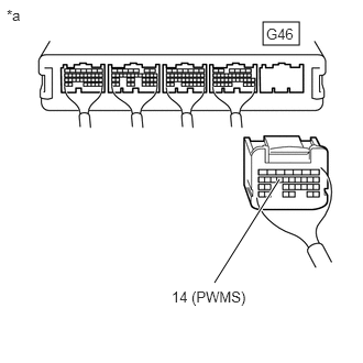
2.49,0.208 2.833,0.427 0.344,0.219 2.031,2.677 2.646,1.698 true 0.063,0.063 0.375,0.26 0.313,0.198 10 false *a 2.521,0.24 2.979,0.438 0.458,0.198 10 false G46 1.625,2.729 2.438,2.896 0.813,0.167 10 false 14 (PWMS)
*a Rear view of wire harness connector
(to ECM)


Disconnect the ECM connector.


b.

Measure the resistance according to the value(s) in the table below.

Standard Resistance:
Tester Connection Switch Condition Specified Condition
G46-14 (PWMS) - Body ground Combination switch (PWR) pushed Below 1 Ω
G46-14 (PWMS) - Body ground Combination switch (PWR) not pushed 10 kΩ or higher


Result:
Proceed to
OK
NG


OK

PROCEED TO NEXT SUSPECTED AREA SHOWN IN PROBLEM SYMPTOMS TABLE

NG

REPAIR OR REPLACE HARNESS OR CONNECTOR