STEERING GEAR / LINKAGE STEERING GEAR REMOVAL
PROCEDURE

 1.PLACE FRONT WHEELS FACING STRAIGHT AHEAD
2.SECURE STEERING WHEEL ASSEMBLY
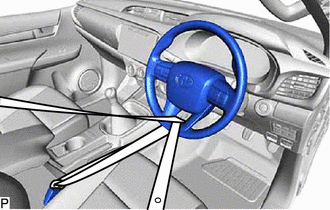
Secure the steering wheel assembly with the seat belt in order to prevent rotation.
- HINT:
-
This operation is useful to prevent damage to the spiral cable sub-assembly.
3.REMOVE FRONT WHEELS
51410
4.REMOVE NO. 1 ENGINE UNDER COVER ASSEMBLY
51442
5.REMOVE NO. 2 ENGINE UNDER COVER
45047
6.DISCONNECT TIE ROD END SUB-ASSEMBLY LH
Remove the cotter pin and nut.
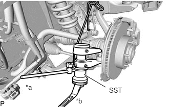
| *a | Hold |
| *b | Turn |
Using SST, disconnect the tie rod end sub-assembly LH from the front axle hub assembly LH.
- SST
- 09628-00011
45046
7.DISCONNECT TIE ROD END SUB-ASSEMBLY RH
- HINT:
-
Use the same procedure described for the LH side.
45219
8.DISCONNECT STEERING SLIDING YOKE
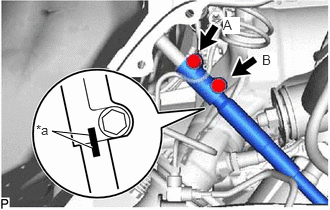
| *a | Matchmark |
Place matchmarks on the steering sliding yoke and No. 2 steering intermediate shaft sub-assembly.
Loosen the bolt labeled A.
Remove the bolt labeled B.
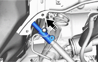

|
Install in this Direction |
Disconnect the steering sliding yoke from the No. 2 steering intermediate shaft sub-assembly.
45203
9.REMOVE NO. 2 STEERING INTERMEDIATE SHAFT SUB-ASSEMBLY
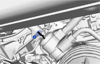
| *a | Matchmark |
Place matchmarks on the No. 2 steering intermediate shaft sub-assembly and power steering link assembly.
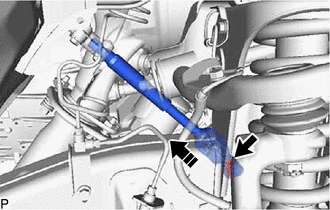
|
|
Install in this Direction |
Remove the bolt and No. 2 steering intermediate shaft sub-assembly from the power steering link assembly.
- NOTICE:
-
If the No. 2 steering intermediate shaft sub-assembly is struck, replace it with a new one.
41110F
10.REMOVE FRONT DIFFERENTIAL CARRIER ASSEMBLY
11.REMOVE POWER STEERING LINK ASSEMBLY
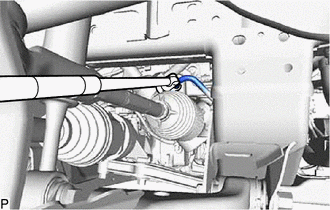
Using a union nut wrench, loosen the flare nut and disconnect the pressure feed tube assembly.
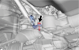
Remove the bolt and disconnect the pressure feed tube assembly bracket from the power steering link assembly.
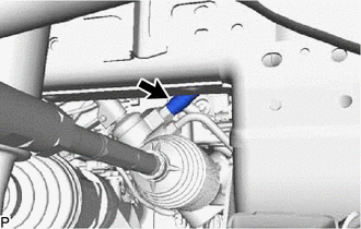
Slide the clip and disconnect the return hose.
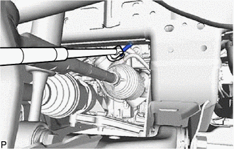
Using a union nut wrench, disconnect the steering gear outlet return tube.
|
|
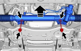
Remove in this Direction |
Fix the 2 nuts in place and remove the 2 bolts and 2 washers. Then remove the power steering link assembly from the front suspension member.
- NOTICE:
-
Never turn the nut. Be sure to turn the bolt.