RM3270E
_52
Drivetrain
_041682
CLUTCH
_0201971
CLUTCH MASTER CYLINDER
G
CLUTCH CLUTCH MASTER CYLINDER ON-VEHICLE INSPECTION
PROCEDURE

 31410
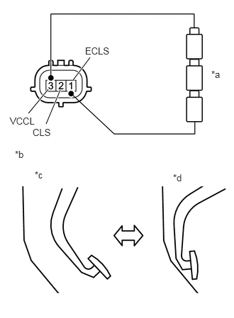
1.INSPECT CLUTCH MASTER CYLINDER ASSEMBLY (w/ Intelligent Manual Transmission Switch)
a.
0.417,1.667 0.708,1.313
true
0.677,1.823 0.885,1.323
true
1.073,1.177 1.323,0.844
true
3.104,1.01 3.417,1.167
0.313,0.156
10
false
*a
0.219,2.188 0.531,2.344
0.313,0.156
10
false
*b
0.51,2.49 0.823,2.646
0.313,0.156
10
false
*c
2.542,2.531 2.854,2.688
0.313,0.156
10
false
*d
0.146,1.698 0.76,1.896
0.615,0.198
10
false
VCCL
1.25,0.667 1.865,0.865
0.615,0.198
10
false
ECLS
0.479,1.865 1.094,2.063
0.615,0.198
10
false
CLS
| *a | Dry Cell Battery |
| *b | Clutch Pedal Condition |
| *c | Released |
| *d | Depressed |
Inspect stroke sensor
i.
Connect the positive (+) end of a series of dry cell batteries to terminal 3 (VCCL) and the negative (-) end to terminal 1 (ECLS), and apply a voltage of 4.5V.
- NOTICE:
-
Do not apply a voltage of 6 V or higher between the terminals.
- HINT:
-
Connect 3 dry cell batteries (1.5 V) in series.
ii.
Measure the voltage between terminals 2 (CLS) and 1 (ECLS) when the clutch pedal is depressed and released with voltage applied.
| Tester Connection | Condition (Clutch Pedal) | Standard |
|---|---|---|
| 2(CLS) - 1(ECLS) | Released | 0.367 to 0.847 V |
| 2(CLS) - 1(ECLS) | Depressed | 3.828 to 4.452 V |
| Tester Connection | Condition (Clutch Pedal) | Standard |
|---|---|---|
| 2(CLS) - 1(ECLS) | Released | 0.5 V |
| 2(CLS) - 1(ECLS) | Depressed | 4.1 V |
If the result is not as specified, there may be a malfunction in the stroke sensor.