SEAT REAR NO. 1 SEAT ASSEMBLY(for 60/40 Split Seat Type RH Side) DISASSEMBLY
CAUTION / NOTICE / HINT
- CAUTION:
- ·
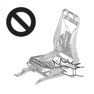
Wear protective gloves. Sharp areas on the parts may injure your hands.
·There is risk of injury.
·Replace any other damaged parts as necessary.
PROCEDURE

 71940A
1.REMOVE REAR SEAT HEADREST ASSEMBLY
Remove the rear seat headrest assembly.
72525A
2.REMOVE RECLINING ADJUSTER RELEASE HANDLE RH
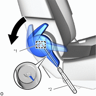
| *1 | Snap Ring |
| *2 | Magnet Hand |
Operate the reclining adjuster release handle RH in the direction indicated by the arrow to align the position of the removal hole shown in the illustration.
Using a magnet hand inserted into the removal hole at the position shown in the illustration, detach the snap ring and remove the reclining adjuster release handle RH.
71843E
3.REMOVE REAR SEAT RECLINING COVER RH
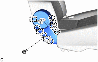
Remove the screw.
Detach the claw and guide and remove the rear seat reclining cover RH.
71843F
4.REMOVE REAR SEAT RECLINING COVER RH
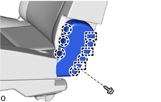
Remove the screw.
Detach the claw and guide and remove the rear seat reclining cover RH.
71931B
5.REMOVE REAR SEAT NO. 1 HEADREST SUPPORT ASSEMBLY
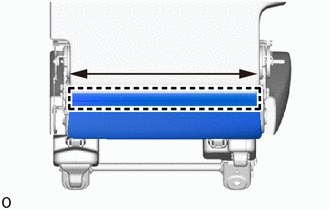
While sliding the part in the direction indicated by the arrow shown in the illustration, detach the J hook.
Pull out the fasteners as shown in the illustration.
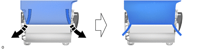

|
Remove in this Direction | - | - |
|
|
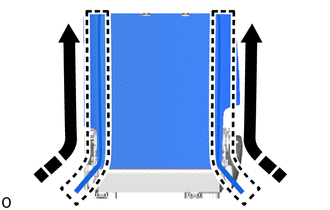
Remove in this Direction |
Open the fasteners as shown in the illustration.
|
|
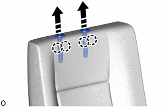
Remove in this Direction |
Pull out direction indicated by the arrow shown in the illustration, detach the claw and remove the 2 rear seat No. 1 headrest support assemblies.
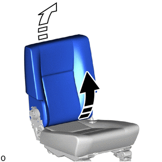
6.REMOVE SEATBACK COVER WITH PAD
|
|
Remove in this Direction (1) |

|
Remove in this Direction (2) |
Pull out the rear end of the seatback cover with pad in removal direction (1) shown in the illustration.
Lift up in removal direction (2) shown in the illustration to remove the seatback cover with pad.
79013
7.REMOVE NO. 1 SEATBACK COVER SUB-ASSEMBLY RH
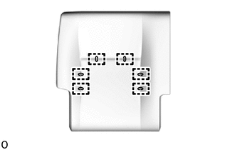
Remove the 6 hog rings and No. 1 seatback cover sub-assembly RH from the No. 1 seatback pad LH.
8.REMOVE SEAT COVER WIRE
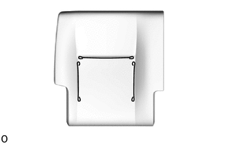
Remove the seat cover wire.
72615A
9.REMOVE REAR SEATBACK LOCK STRIKER COVER RH
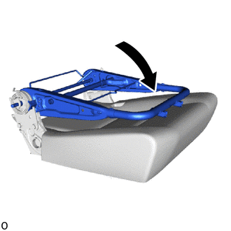
Move the No. 1 seatback frame sub-assembly RH in the direction indicated by the arrow shown in the illustration.
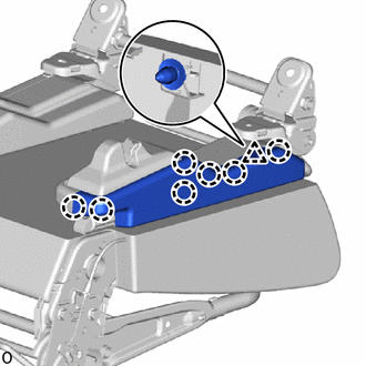
Detach the claw and clip and remove the rear seatback look striker cover RH.
72617
10.REMOVE SEATBACK LOCK STRIKER COVER RETAINER
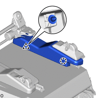
Detach the claw and clip and remove the seatback look striker cover retainer.
72615A
11.REMOVE REAR SEATBACK LOCK STRIKER COVER RH
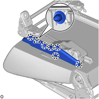
Detach the claw and clip and remove the rear seatback look striker cover RH.
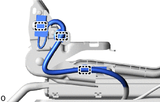
Detach the clamp.
72617
12.REMOVE SEATBACK LOCK STRIKER COVER RETAINER
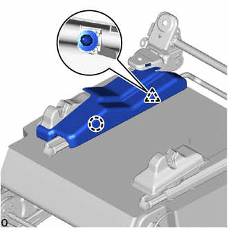
Detach the claw and clip and remove the seatback look striker cover retainer.
72665C
13.REMOVE REAR SEAT LOCK COVER RH
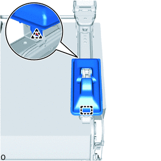
Detach the clip.
Detach the guide and remove the rear seat lock cover RH.
72665C
14.REMOVE REAR SEAT LOCK COVER RH
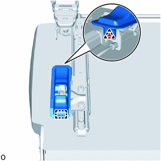
Detach the clip.
Detach the guide and remove the rear seat lock cover RH.
79105
15.REMOVE NO. 1 SEAT LEG SUB-ASSEMBLY RH
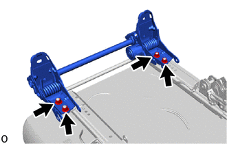
Remove the No. 1 seat leg sub-assembly RH with 4 bolts.
72650A
16.REMOVE REAR SEAT LOCK ASSEMBLY RH
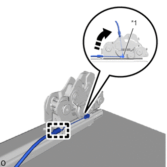
| *1 | Cable End |
|
|
Remove in this Direction |
Detach the casing cap.
Turn the cable end in the removal direction shown in the illustration and disconnect the cable end.
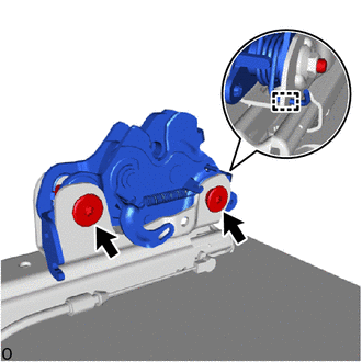
Detach the hook.
Using a T55 "TORX" socket wrench, remove the 2 "TORX" bolts and rear seat lock assembly RH.
72650A
17.REMOVE REAR SEAT LOCK ASSEMBLY RH
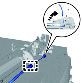
| *1 | Cable End |
|
|
Remove in this Direction |
Detach the casing cap.
Turn the cable end in the removal direction shown in the illustration and disconnect the cable end.
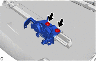
Using a T55 "TORX" socket wrench, remove the 2 "TORX" bolts and rear seat lock assembly RH.
72201A
18.REMOVE SEAT TRACK HANDLE SUB-ASSEMBLY RH
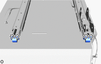
Detach the claw.
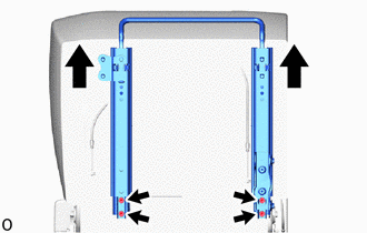
Slide the rear seat inner track assembly RH and rear seat outer track assembly RH in the direction indicated by the arrow as shown in the illustration and remove the 4 bolts.
Insert a screwdriver with its tip wrapped with protective tape into the removal hole of the rear seat inner track assembly RH in the direction indicated by the arrow shown in the illustration. Then, while pulling the screwdriver as shown, detach the lock spring.
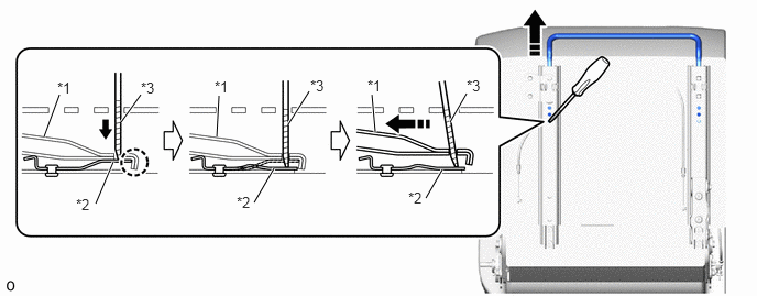
| *1 | Seat Track Handle Sub-Assembly RH | *2 | Lock Spring |
| *3 | Protective Tape | - | - |
|
|
Remove in this Direction | - | - |
Insert a screwdriver with its tip wrapped with protective tape into the removal hole of the rear seat outer track assembly RH in the direction indicated by the arrow shown in the illustration. Then, while pulling the screwdriver as shown, detach the lock spring.
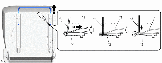
| *1 | Seat Track Handle Sub-Assembly RH | *2 | Lock Spring |
| *3 | Protective Tape | - | - |
|
|
Remove in this Direction | - | - |
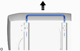
|
|
Remove in this Direction |
Pull up the seat track handle sub-assembly RH as shown in the illustration to remove it.
72180
19.REMOVE REAR SEAT INNER TRACK ASSEMBLY RH
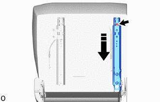
|
|
Remove in this Direction |
Slide the rail and remove the bolt and rear seat outer track assembly RH as shown in the illustration.
72160
20.REMOVE REAR SEAT OUTER TRACK ASSEMBLY RH
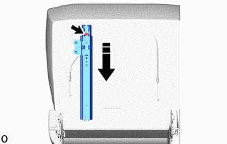
|
|
Remove in this Direction |
Slide the rail and remove the bolt and rear seat outer track assembly RH as shown in the illustration.
73380C
21.REMOVE REAR NO. 1 SEAT INNER BELT ASSEMBLY RH
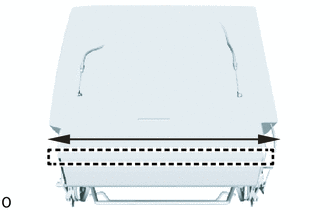
While sliding the part in the direction indicated by the arrow shown in the illustration, detach the J hook.
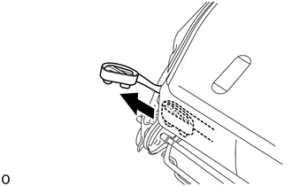
Pull out the No. 1 fold seat stopper band assembly from the rear end of the seat cushion cover with pad.
Pull out the fasteners as shown in the illustration.
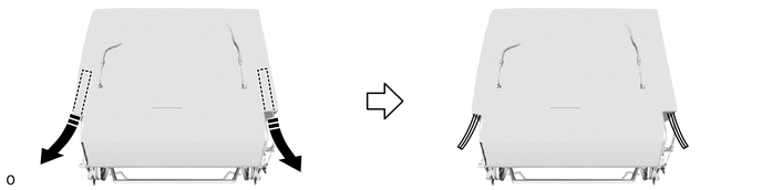
|
|
Remove in this Direction | - | - |
|
|
Remove in this Direction |
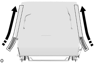
Open the fasteners as shown in the illustration.
|
|
Remove in this Direction |
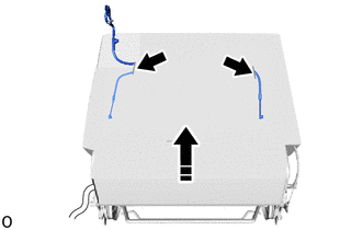
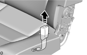
While opening the No. 1 seat cushion cover sub-assembly, pull out the rear No. 1 seat lock cable assembly and the rear No. 1 seat inner belt assembly RH from the slit as shown in the illustration.
|
|
Remove in this Direction |
Remove the rear No. 1 seat inner belt assembly RH from the hole of the rear seat cushion cover with pad RH as shown in the illustration.
22.REMOVE SEAT CUSHION COVER WITH PAD
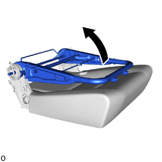
Move the No. 1 seatback frame sub-assembly RH in the direction indicated by the arrow shown in the illustration.
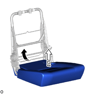
|
|
Remove in this Direction (1) |
|
|
Remove in this Direction (2) |
Pull out the rear end of the seat cushion cover with pad in removal direction (1) shown in the illustration.
Lift up in removal direction (2) shown in the illustration to remove the seat cushion cover with pad.
79011
23.REMOVE NO. 1 SEAT CUSHION COVER SUB-ASSEMBLY RH
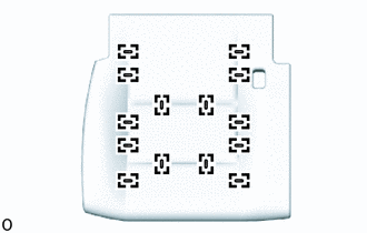
Remove the 14 hog rings and No. 1 seat cushion cover sub-assembly RH from the No. 1 seat cushion pad RH.
24.REMOVE SEAT COVER WIRE
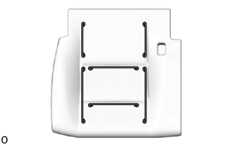
Remove the seat cover wire.
72666D
25.REMOVE REAR SEAT LOCK COVER RH
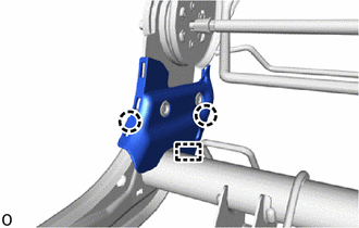
Detach the claw and guide and remove the rear seat lock cover RH.
72666
26.REMOVE REAR SEATBACK LOCK COVER LH
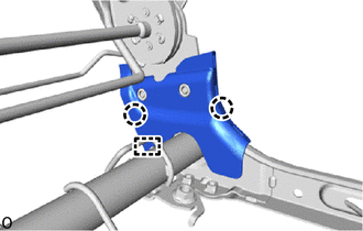
Detach the claw and guide and remove the rear seatback lock cover LH.
79103A
27.REMOVE NO. 1 SEATBACK FRAME SUB-ASSEMBLY RH
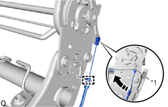
| *1 | Cable End |
|
|
Remove in this Direction |
Detach the casing cap.
Turn the cable end in the removal direction shown in the illustration and disconnect the cable end.
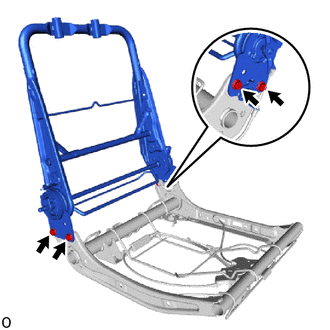
Remove the No. 1 seatback frame sub-assembly RH with 4 bolts.
78950
28.REMOVE NO. 1 FOLD SEAT STOPPER BAND ASSEMBLY
|
|
Remove in this Direction |
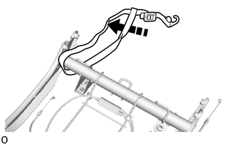
Pull out and remove the No. 1 fold seat stopper band assembly as shown in the illustration.
78910B
29.REMOVE NO. 1 FOLD SEAT LOCK CONTROL CABLE ASSEMBLY RH
| *1 | Cable End |
|
|
Remove in this Direction |
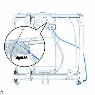
Detach the casing cap.
Turn the cable end in the removal direction shown in the illustration and disconnect the cable end and remove the No. 1 fold seat lock control cable assembly RH.
72620B
30.REMOVE REAR NO. 1 SEAT LOCK CABLE ASSEMBLY
| *1 | Protective Tape |
|
|
Remove in this Direction |
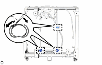
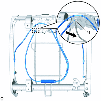
Move a screwdriver with its tip wrapped with protective tape in the direction indicated by the arrow to widen and remove the 3 wiring harness clamps as shown in the illustration.
| *1 | Cable End |
|
|
Remove in this Direction |
Detach the casing cap.
Turn the cable end as shown in the illustration, disconnect the cable end and remove the rear No. 1 seat lock cable assembly.