SEAT REAR NO. 1 SEAT ASSEMBLY(for 60/40 Split Seat Type RH Side) REASSEMBLY
CAUTION / NOTICE / HINT
- CAUTION:
- ·
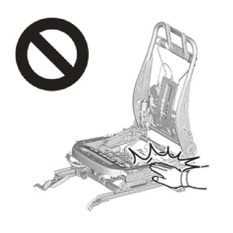
Wear protective gloves. Sharp areas on the parts may injure your hands.
·There is risk of injury.
·Replace any other damaged parts as necessary.
PROCEDURE

 72620B
1.INSTALL REAR NO. 1 SEAT LOCK CABLE ASSEMBLY
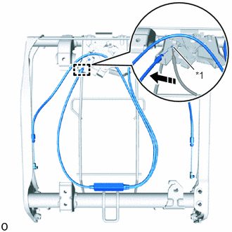
| *1 | Cable End |

|
Install in this Direction |
Turn the cable end in the installation direction shown in the illustration to install the cable end.
Attach the casing cap.
- HINT:
-
Install at the gray casing cap side.
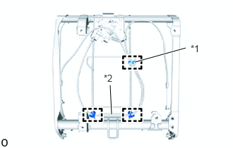
| *1 | Wiring Harness Clamp A |
| *2 | Joint Case |
Attach the 3 wiring harness clamps to rear No. 1 seat lock cable assembly.
- HINT:
- ·
Secure wiring harness clamp A to the vertical wire of the seat cushion.
- ·
Secure the joint case between the wires.
78910B
2.INSTALL NO. 1 FOLD SEAT LOCK CONTROL CABLE ASSEMBLY RH
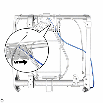
| *1 | Cable End |
|
|
Install in this Direction |
Turn the cable end in the installation direction shown in the illustration to install the cable end.
Attach the casing cap and install the No. 1 fold seat lock control cable assembly RH.
78950
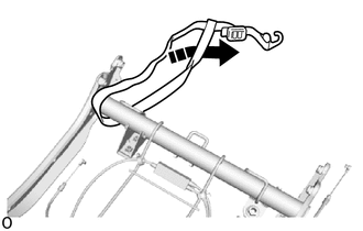
3.INSTALL NO. 1 FOLD SEAT STOPPER BAND ASSEMBLY
|
|
Install in this Direction |
Pass the No. 1 fold seat stopper band assembly through itself to install it as shown in the illustration.
79103A
4.INSTALL NO. 1 SEATBACK FRAME SUB-ASSEMBLY RH
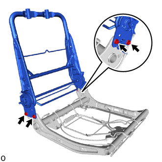
Install the No. 1 seatback frame sub-assembly RH with 4 bolts.
- Torque:
- 42 N*m (428 kgf*cm, 31 ft.*lbf)
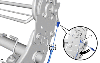
| *1 | Cable End |
|
|
Install in this Direction |
Turn the cable end in the installation direction shown in the illustration to install the cable end.
Attach the casing cap.
72666
5.INSTALL REAR SEATBACK LOCK COVER LH
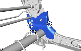
Attach the claw and guide to install the rear seatback lock cover LH.
72666D
6.INSTALL REAR SEAT LOCK COVER RH
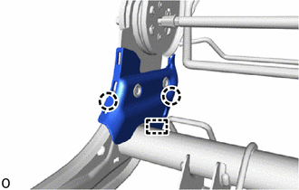
Attach the claw and guide to install the rear seat lock cover RH.
7.INSTALL SEAT COVER WIRE
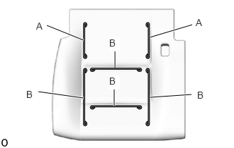
Install the seat cover wire.
- HINT:
- ·
Wire 1000 mm (3.28 ft.) or longer and shaped wire are available as supplied parts.
- ·
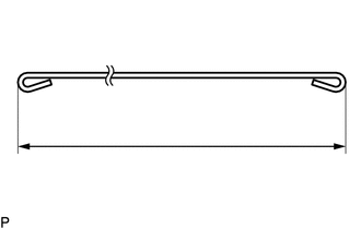
When a wire that is less than 1000 mm (3.28 ft.) in length is needed, cut or shape 1000 mm (3.28 ft.) wire into the dimensions shown in the illustration.
- ·
Make sure to read the precautions before preparing the wire.
Click hereVehicle Interior>SEAT>FRONT SEAT ASSEMBLY(for Manual Seat)>PRECAUTION
| A | 150 mm (5.91 in.) |
| B | 270 mm (10.63 in.) |
- HINT:
-
-
The dimensions shown in the illustration are the lengths.
79011
8.INSTALL NO. 1 SEAT CUSHION COVER SUB-ASSEMBLY RH
- HINT:
- ·
When installing the No. 1 seat cushion cover sub-assembly RH, refer to the precautions in order to prevent wrinkles from forming.
Click hereVehicle Interior>SEAT>FRONT SEAT ASSEMBLY(for Manual Seat)>PRECAUTION
- ·
Align the seam allowance in a single direction as shown in the illustration.
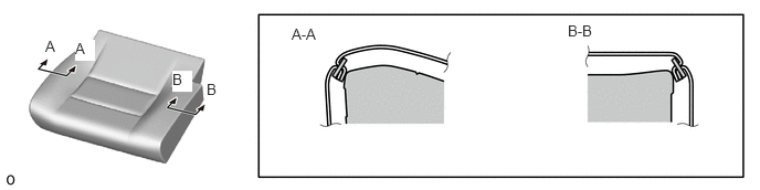 0.427,0.354 0.615,0.552 0.188,0.198 10 true A 0.708,0.375 0.896,0.573 0.188,0.198 10 true A 1.625,0.667 1.813,0.865 0.188,0.198 10 true B 1.948,0.76 2.135,0.958 0.188,0.198 10 true B 2.75,0.24 3.208,0.438 0.458,0.198 10 false A-A 5.354,0.208 5.813,0.406 0.458,0.198 10 false B-B
Set the No. 1 seat cushion cover sub-assembly RH.
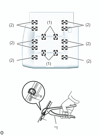
| *1 | Hog Ring Pliers |
| *a | Cutout |
Using hog ring pliers, install the No. 1 seat cushion cover sub-assembly RH to the No. 1 seat cushion pad RH with 14 new hog rings in the order indicated in the illustration.
- NOTICE:
- ·
Be careful not to damage the No. 1 seat cushion cover sub-assembly RH.
- ·
Be sure to securely install the hog rings as shown in the illustration while preventing wrinkles from forming on the No. 1 seat cushion cover sub-assembly RH.
- HINT:
-
Install the hog rings at the cutouts if they are there.
9.INSTALL SEAT CUSHION COVER WITH PAD
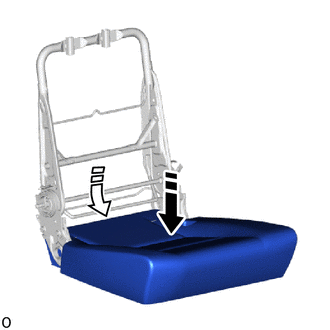
|
|
Install in this Direction (1) |

|
Install in this Direction (2) |
Push in installation direction (1) shown in the illustration to temporarily install the seat cushion cover with pad.
Install the seat cushion cover with pad in the installation direction (2) so that the rear end is held in place.
73380C
10.INSTALL REAR NO. 1 SEAT INNER BELT ASSEMBLY RH
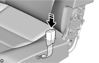
|
|
Install in this Direction |
Pass the rear No. 1 seat inner belt assembly RH through the hole of the rear seat cushion cover with pad RH as shown in the illustration.
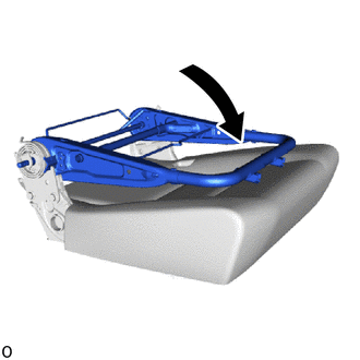
Move the No. 1 seatback frame sub-assembly LH in the direction indicated by the arrow shown in the illustration.
Install the rear No. 1 seat inner belt assembly RH with the bolt.
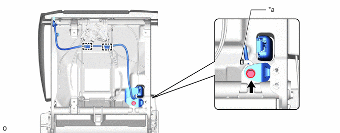
| *a | Protruding Part | - | - |
- Torque:
- 42 N*m (428 kgf*cm, 31 ft.*lbf)
- NOTICE:
-
The anchor part of the rear No. 1 seat inner belt assembly RH must not overlap the protruding part.
Attach the clamp.
|
|
Install in this Direction |
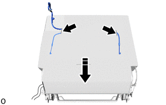
While closing the back of the seat cushion cover with pad as shown in the illustration, pull out the rear seat lock assembly installation part of the rear No. 1 seat lock cable assembly and the rear No. 1 seat inner belt assembly RH from the slit.
|
|
Install in this Direction |
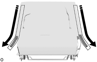
Close the fasteners as shown in the illustration.
Push in the closed fasteners as shown in the illustration.
|
|
Install in this Direction | - | - |
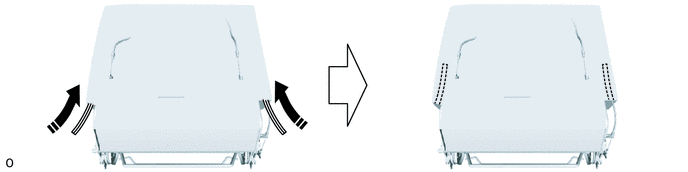
Roll up the No. 1 fold seat stopper band assembly toward the rear end of the seat cushion with pad and push it into the seat cushion with pad in the direction indicated by the arrow shown in the illustration.
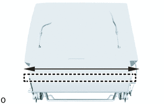
While sliding the part in the direction indicated by the arrow shown in the illustration, install the J hook.
72160
11.INSTALL REAR SEAT OUTER TRACK ASSEMBLY RH
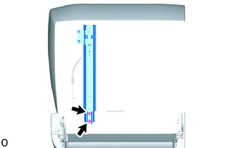
Temporarily install the rear seat outer track assembly RH with the 2 bolts until it contacts the part.
|
|
Install in this Direction |
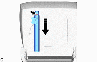
Slide the rail and install the rear seat outer track assembly RH with the bolt as shown in the illustration.
- Torque:
- 29 N*m (296 kgf*cm, 21 ft.*lbf)
72180
12.INSTALL REAR SEAT INNER TRACK ASSEMBLY RH
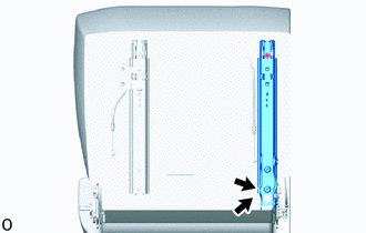
Temporarily install the rear seat inner track assembly RH with the 2 bolts until it contacts the part.
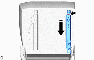
|
|
Install in this Direction |
Slide the rail and install the rear seat inner track assembly RH with the bolt as shown in the illustration.
- Torque:
- 29 N*m (296 kgf*cm, 21 ft.*lbf)
72201A
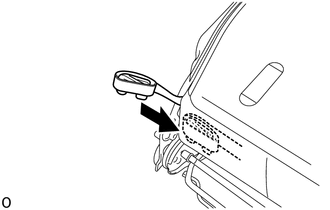
13.INSTALL SEAT TRACK HANDLE SUB-ASSEMBLY RH
Push in the seat track handle sub-assembly RH to attach the lock spring and install the seat track handle sub-assembly as shown in the illustration.
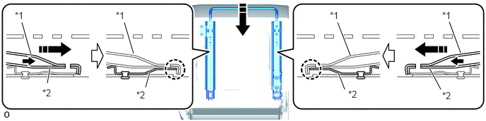
| *1 | Seat Track Handle Sub-Assembly RH | *2 | Lock Spring |
|
|
Install in this Direction | - | - |
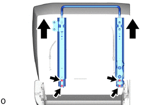
Slide the rear seat inner track assembly RH and rear seat outer track assembly RH in the direction indicated by the arrow as shown in the illustration and tighten the 4 bolts.
- Torque:
- 29 N*m (296 kgf*cm, 21 ft.*lbf)
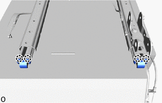
Attach the claw.
72650A
14.INSTALL REAR SEAT LOCK ASSEMBLY RH
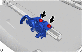
Using a T55 "TORX" socket wrench, install the 2 "TORX" bolts and rear seat lock assembly RH.
- Torque:
- 29 N*m (296 kgf*cm, 21 ft.*lbf)
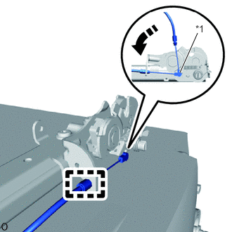
| *1 | Cable End |
|
|
Install in this Direction |
Turn the cable end in the installation direction shown in the illustration to install the cable end.
Attach the casing cap.
- HINT:
-
Install at the purple casing cap side.
72650A
15.INSTALL REAR SEAT LOCK ASSEMBLY RH
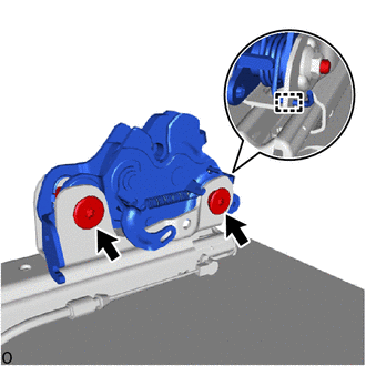
Using a T55 "TORX" socket wrench, install the 2 "TORX" bolts and rear seat lock assembly RH.
- Torque:
- 29 N*m (296 kgf*cm, 21 ft.*lbf)
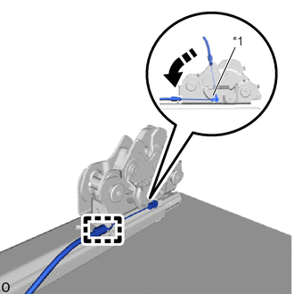
| *1 | Cable End |
|
|
Install in this Direction |
Turn the cable end in the installation direction shown in the illustration to install the cable end.
Attach the casing cap.
- HINT:
-
Install at the yellow casing cap side.
79105
16.INSTALL NO. 1 SEAT LEG SUB-ASSEMBLY RH
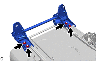
Install the No. 1 seat leg sub-assembly RH with 4 bolts.
- Torque:
- 42 N*m (428 kgf*cm, 31 ft.*lbf)
72665C
17.INSTALL REAR SEAT LOCK COVER RH
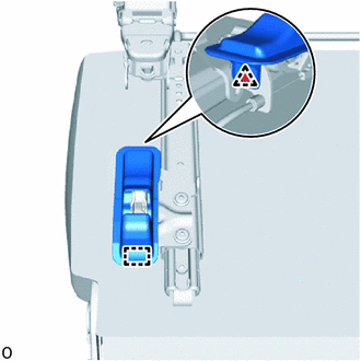
Attach the guide.
Attach the clip to install the rear seat lock cover RH.
72665C
18.INSTALL REAR SEAT LOCK COVER RH
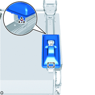
Attach the guide.
Attach the clip to install the rear seat lock cover RH.
72617
19.INSTALL SEATBACK LOCK STRIKER COVER RETAINER
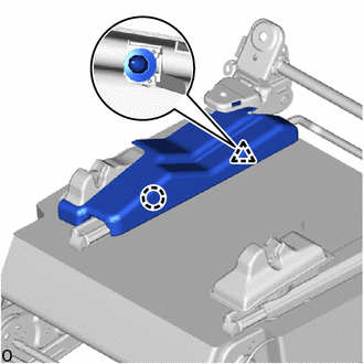
Attach the claw and clip to install the seatback lock striker cover retainer.
72615A
20.INSTALL REAR SEATBACK LOCK STRIKER COVER RH
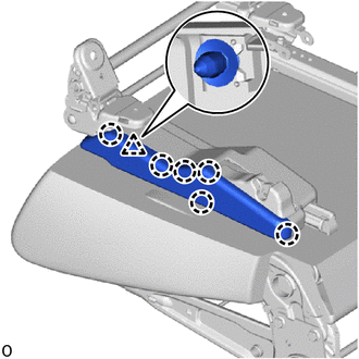
Attach the claw and clip to install the rear seatback lock striker cover RH.
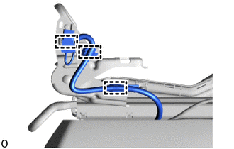
Attach the clamp.
72617
21.INSTALL SEATBACK LOCK STRIKER COVER RETAINER
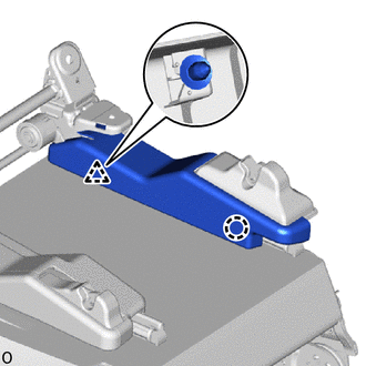
Attach the claw and clip to install the seatback lock striker cover retainer.
72615A
22.INSTALL REAR SEATBACK LOCK STRIKER COVER RH
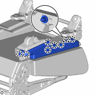
Attach the claw and clip to install the rear seatback look striker cover RH.
23.INSTALL SEAT COVER WIRE
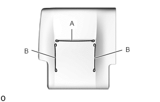
Install the seat cover wire.
- HINT:
- ·
Wire 1000 mm (3.28 ft.) or longer and shaped wire are available as supplied parts.
- ·
When a wire that is less than 1000 mm (3.28 ft.) in length is needed, cut or shape 1000 mm (3.28 ft.) wire into the dimensions shown in the illustration.
- ·
Make sure to read the precautions before preparing the wire.
Click hereVehicle Interior>SEAT>FRONT SEAT ASSEMBLY(for Manual Seat)>PRECAUTION
- Length:
A 270 mm (10.63 in.) B 290 mm (11.42 in.)
- HINT:
-
-
The dimensions shown in the illustration are the lengths.
79013
24.INSTALL NO. 1 SEATBACK COVER SUB-ASSEMBLY RH
- HINT:
- ·
When installing the No. 1 seatback cover sub-assembly RH, refer to the precautions in order to prevent wrinkles from forming.
Click hereVehicle Interior>SEAT>FRONT SEAT ASSEMBLY(for Manual Seat)>PRECAUTION
- ·
Align the seam allowance in a single direction as shown in the illustration.
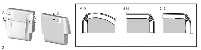 0.073,0.365 0.229,0.563 0.156,0.198 10 true A 0.292,0.417 0.448,0.615 0.156,0.198 10 true A 0.979,0.49 1.135,0.688 0.156,0.198 10 true C 1.208,0.531 1.365,0.729 0.156,0.198 10 true C 2.021,0.385 2.177,0.583 0.156,0.198 10 true B 2.021,0.635 2.177,0.833 0.156,0.198 10 true B 2.844,0.219 3.302,0.417 0.458,0.198 10 false A-A 4.365,0.219 4.823,0.417 0.458,0.198 10 false B-B 5.698,0.219 6.156,0.417 0.458,0.198 10 false C-C
Set the No. 1 seatback cover sub-assembly RH.
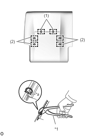
| *1 | Hog Ring Pliers |
| *a | Cutout |
Using hog ring pliers, install the No. 1 seatback cover sub-assembly RH to the No. 1 seatback pad RH with 6 new hog rings in the order indicated in the illustration.
- NOTICE:
- ·
Be careful not to damage the No. 1 seatback cover sub-assembly RH.
- ·
Be sure to securely install the hog rings as shown in the illustration while preventing wrinkles from forming on the No. 1 seatback cover sub-assembly RH.
- HINT:
-
Install the hog rings at the cutouts if they are there.
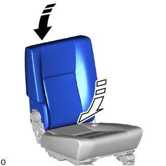
25.INSTALL SEATBACK COVER WITH PAD
|
|
Install in this Direction (1) |
|
|
Install in this Direction (2) |
While aligning the top, push in the seatback cover with pad in the installation direction (1).
Push in the bottom left side of the seatback cover with pad in the installation direction (2).
71931B
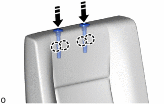
26.INSTALL REAR SEAT NO. 1 HEADREST SUPPORT ASSEMBLY
|
|
Install in this Direction |
Push in the installation direction shown in the illustration to attach the claw and install the 2 rear No. 1 headrest support assemblies.
|
|
Install in this Direction |
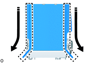
Close the fasteners as shown in the illustration.
Push in the fasteners as shown in the illustration.
|
|
Install in this Direction | - | - |
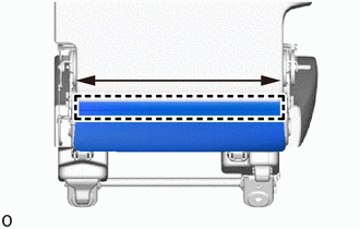
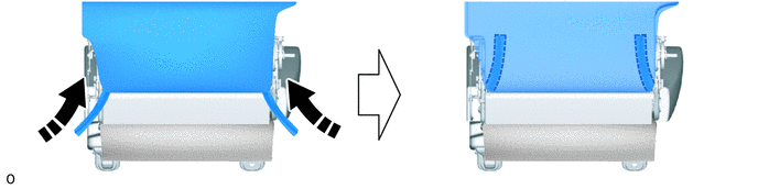
While sliding the part in the direction indicated by the arrow shown in the illustration, attach the J hook.
71843F
27.INSTALL REAR SEAT RECLINING COVER RH
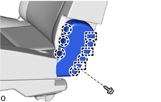
Attach the claw and guide.
Install the rear seat reclining cover RH with screw.
71843E
28.INSTALL REAR SEAT RECLINING COVER RH
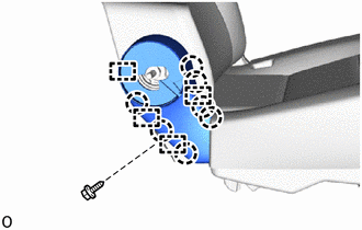
Attach the claw and guide.
Install the and rear seat reclining cover RH with screw.
72525A
29.INSTALL RECLINING ADJUSTER RELEASE HANDLE RH
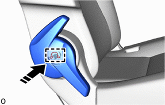
|
|
Install in this Direction |
Install the snap ring to the reclining adjuster release handle RH.
Push the reclining adjuster release handle RH as shown in the illustration to attach the guide and install the reclining adjuster release handle RH.
71940A
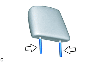
30.INSTALL REAR SEAT HEADREST ASSEMBLY

|
Apply Silicon |
Apply silicon lubricant in this range.
Install the rear seat headrest assembly.