EXTERIOR PANELS / TRIM SIDE STEP REASSEMBLY
CAUTION / NOTICE / HINT
- HINT:
- ·
Use the same procedure for the RH and LH sides.
·The procedure listed below is for the LH side.
PROCEDURE

 51082
1.INSTALL NO. 1 SIDE STEP STAY SUB-ASSEMBLY LH
Install the No. 2 nose piece to an air riveter or hand riveter.
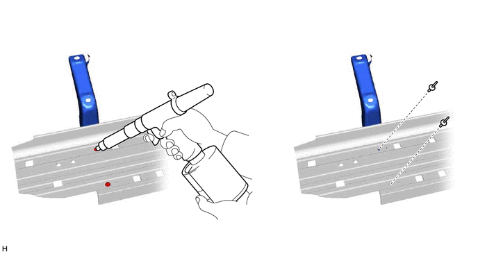
Insert the mandrel part of 2 new rivets into the nose piece.
Using the riveter, install the No. 1 side step stay sub-assembly LH to the step plate LH with the 2 rivets as shown in the illustration.
- NOTICE:
- ·
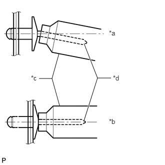 1.229,1.115 1.083,1.635 1.083,1.635 1.24,2.198 false 1.083,1.635 0.813,1.635 false 1.75,0.906 2.031,1.625 2.031,1.625 1.75,2.51 true 2.031,1.625 2.313,1.625 false 2.271,0.604 2.542,0.854 0.271,0.25 10 false *a 2.271,2.448 2.521,2.667 0.25,0.219 10 false *b 0.646,1.542 0.927,1.771 0.281,0.229 10 false *c 2.354,1.542 2.656,1.802 0.302,0.26 10 false *d
*a INCORRECT *b CORRECT *c Riveter *d Mandrel
Do not pry the rivet with the riveter as this will cause damage to the riveter and mandrel.
·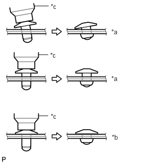 0.719,0.125 1.021,0.125 false 0.813,1.146 1.01,1.146 false 0.813,2.427 1.01,2.427 false 2.333,0.583 2.771,1.01 0.438,0.427 10 false *a 2.333,1.563 2.719,1.844 0.385,0.281 10 false *a 2.344,2.792 2.74,3.073 0.396,0.281 10 false *b 1.063,2.354 1.292,2.583 0.229,0.229 10 false *c 1.052,1.073 1.385,1.323 0.333,0.25 10 false *c 1.063,0.052 1.344,0.281 0.281,0.229 10 false *c
*a INCORRECT *b CORRECT *c Riveter
Confirm that the rivets are seated properly against the No. 1 side step stay.
·Do not tilt the riveter when installing the rivet to the No. 1 side step stay.
·Do not leave any space between the rivet head and No. 1 side step stay.
·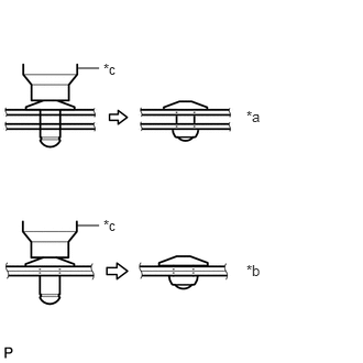 0.74,0.646 0.938,0.646 false 0.729,2.135 0.938,2.135 false 2.333,1.021 2.583,1.302 0.25,0.281 10 false *a 2.333,2.479 2.583,2.729 0.25,0.25 10 false *b 0.979,0.573 1.26,0.792 0.281,0.219 10 false *c 0.979,2.052 1.292,2.323 0.313,0.271 10 false *c
*a INCORRECT *b CORRECT *c Riveter
Do not leave any space between the No. 1 side step stay and step plate. Firmly hold together the 2 items while installing the rivet.
51796
2.INSTALL NO. 2 SIDE STEP BRACKET LH
Install the No. 2 nose piece to an air riveter or hand riveter.
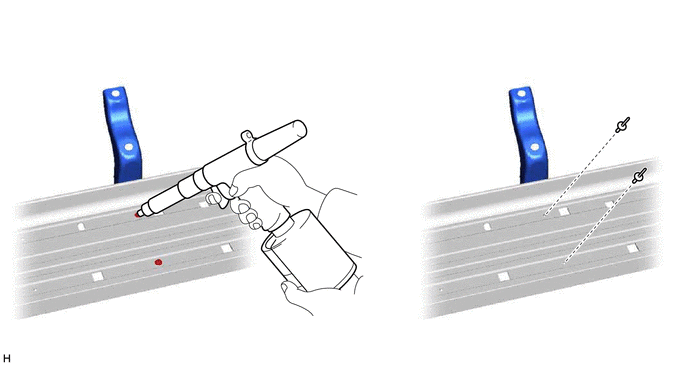
Insert the mandrel part of 2 new rivets into the nose piece.
Using the riveter, install the No. 2 side step bracket LH to the step plate LH with the 2 rivets as shown in the illustration.
- NOTICE:
- ·
1.229,1.115 1.083,1.635 1.083,1.635 1.24,2.198 false 1.083,1.635 0.813,1.635 false 1.75,0.906 2.031,1.625 2.031,1.625 1.75,2.51 true 2.031,1.625 2.313,1.625 false 2.271,0.604 2.542,0.854 0.271,0.25 10 false *a 2.271,2.448 2.521,2.667 0.25,0.219 10 false *b 0.646,1.542 0.927,1.771 0.281,0.229 10 false *c 2.354,1.542 2.656,1.802 0.302,0.26 10 false *d
*a INCORRECT *b CORRECT *c Riveter *d Mandrel
Do not pry the rivet with the riveter as this will cause damage to the riveter and mandrel.
·
0.719,0.125 1.021,0.125 false 0.813,1.146 1.01,1.146 false 0.813,2.427 1.01,2.427 false 2.333,0.583 2.771,1.01 0.438,0.427 10 false *a 2.333,1.563 2.719,1.844 0.385,0.281 10 false *a 2.344,2.792 2.74,3.073 0.396,0.281 10 false *b 1.063,2.354 1.292,2.583 0.229,0.229 10 false *c 1.052,1.073 1.385,1.323 0.333,0.25 10 false *c 1.063,0.052 1.344,0.281 0.281,0.229 10 false *c*a INCORRECT *b CORRECT *c Riveter
Confirm that the rivets are seated properly against the No. 2 side step bracket.
·Do not tilt the riveter when installing the rivet to the No. 2 side step bracket.
·Do not leave any space between the rivet head and No. 2 side step bracket.
·
0.74,0.646 0.938,0.646 false 0.729,2.135 0.938,2.135 false 2.333,1.021 2.583,1.302 0.25,0.281 10 false *a 2.333,2.479 2.583,2.729 0.25,0.25 10 false *b 0.979,0.573 1.26,0.792 0.281,0.219 10 false *c 0.979,2.052 1.292,2.323 0.313,0.271 10 false *c*a INCORRECT *b CORRECT *c Riveter
Do not leave any space between the No. 2 side step bracket and step plate. Firmly hold together the 2 items while installing the rivet.
51798
3.INSTALL NO. 3 SIDE STEP BRACKET LH
Install the No. 2 nose piece to an air riveter or hand riveter.
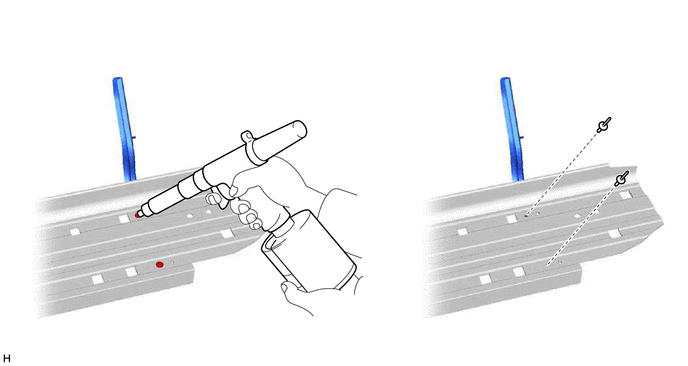
Insert the mandrel part of 2 new rivets into the nose piece.
Using the riveter, install the No. 3 side step bracket LH to the step plate LH with the 2 rivets as shown in the illustration.
- NOTICE:
- ·
1.229,1.115 1.083,1.635 1.083,1.635 1.24,2.198 false 1.083,1.635 0.813,1.635 false 1.75,0.906 2.031,1.625 2.031,1.625 1.75,2.51 true 2.031,1.625 2.313,1.625 false 2.271,0.604 2.542,0.854 0.271,0.25 10 false *a 2.271,2.448 2.521,2.667 0.25,0.219 10 false *b 0.646,1.542 0.927,1.771 0.281,0.229 10 false *c 2.354,1.542 2.656,1.802 0.302,0.26 10 false *d
*a INCORRECT *b CORRECT *c Riveter *d Mandrel
Do not pry the rivet with the riveter as this will cause damage to the riveter and mandrel.
·
0.719,0.125 1.021,0.125 false 0.813,1.146 1.01,1.146 false 0.813,2.427 1.01,2.427 false 2.333,0.583 2.771,1.01 0.438,0.427 10 false *a 2.333,1.563 2.719,1.844 0.385,0.281 10 false *a 2.344,2.792 2.74,3.073 0.396,0.281 10 false *b 1.063,2.354 1.292,2.583 0.229,0.229 10 false *c 1.052,1.073 1.385,1.323 0.333,0.25 10 false *c 1.063,0.052 1.344,0.281 0.281,0.229 10 false *c*a INCORRECT *b CORRECT *c Riveter
Confirm that the rivets are seated properly against the No. 3 side step bracket.
·Do not tilt the riveter when installing the rivet to the No. 3 side step bracket.
·Do not leave any space between the rivet head and No. 3 side step bracket.
·
0.74,0.646 0.938,0.646 false 0.729,2.135 0.938,2.135 false 2.333,1.021 2.583,1.302 0.25,0.281 10 false *a 2.333,2.479 2.583,2.729 0.25,0.25 10 false *b 0.979,0.573 1.26,0.792 0.281,0.219 10 false *c 0.979,2.052 1.292,2.323 0.313,0.271 10 false *c*a INCORRECT *b CORRECT *c Riveter
Do not leave any space between the No. 3 side step bracket and step plate. Firmly hold together the 2 items while installing the rivet.
51774C
4.INSTALL STEP PLATE COVER LH
Attach the claw and guide and install the step plate cover LH.
Install the 2 bolts.
- Torque:
- 4.0 N*m (41 kgf*cm, 35 in.*lbf)