DRIVE SHAFT / PROPELLER SHAFT FRONT PROPELLER SHAFT ASSEMBLY(except TSAM Made) REASSEMBLY
CAUTION / NOTICE / HINT
- NOTICE:
- ·
When using a vise, place aluminum plates between the part and vise.
·When using a vise, do not overtighten it.
PROCEDURE

 1.INSTALL SPIDER BEARING
- HINT:
-
Use the same procedure for both spiders.
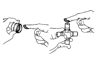
Apply grease to a new spider and new spider bearings.
- Grease:
Lithium base chassis grease NLGI No. 2
- NOTICE:
-
Do not apply too much grease.
Install the spider to the flange yoke.
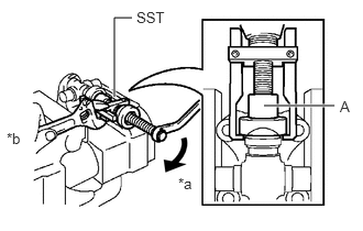
| *a | Turn |
| *b | Hold |
Using SST, install 2 of the spider bearings to the spider.
- SST
- 09332-25010
- HINT:
-
Before installing SST, sufficiently raise the part labeled A. If the part labeled A is too low, it may be difficult to install SST.
Using SST, adjust both spider bearings so that the snap ring grooves are as wide as possible and equal in width.
- SST
- 09332-25010
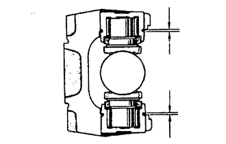
Install 2 new snap rings to the installed spider bearings. The snap rings must have equal thickness and allow 0 to 0.05 mm (0 to 0.00196 in.) of axial play.
- NOTICE:
-
While the installed snap rings should have equal thickness, if the axial play is greater than 0.05 mm (0.00196 in.), select 2 snap rings that have as close to the same thickness as possible.
- HINT:
-
Do not reuse the snap rings.
| Part No. | Mark | Thickness |
|---|---|---|
| 90520-T0007 | F | 2.18 to 2.20 mm (0.0859 to 0.0866 in.) |
| 90520-T0008 | G | 2.20 to 2.22 mm (0.0867 to 0.0874 in.) |
| 90520-T0009 | H | 2.22 to 2.24 mm (0.0875 to 0.0881 in.) |
| 90520-T0010 | J | 2.24 to 2.26 mm (0.0882 to 0.0889 in.) |
| 90520-T0011 | K | 2.26 to 2.28 mm (0.0890 to 0.0897 in.) |
| 90520-T0012 | 1 | 2.28 to 2.30 mm (0.0898 to 0.0905 in.) |
| 90520-T0013 | 2 | 2.30 to 2.32 mm (0.0906 to 0.0913 in.) |
| 90520-T0014 | 3 | 2.32 to 2.34 mm (0.0914 to 0.0921 in.) |
| 90520-T0015 | 4 | 2.34 to 2.36 mm (0.0922 to 0.0929 in.) |
| 90520-T0016 | 5 | 2.36 to 2.38 mm (0.0930 to 0.0937 in.) |
| 90520-T0017 | 6 | 2.38 to 2.40 mm (0.0938 to 0.0944 in.) |
| 90520-T0018 | 7 | 2.40 to 2.42 mm (0.0945 to 0.0952 in.) |
| 90520-T0019 | 8 | 2.42 to 2.44 mm (0.0953 to 0.0960 in.) |
| 90520-T0020 | N | 2.44 to 2.46 mm (0.0961 to 0.0968 in.) |
| 90520-T0021 | 10 | 2.46 to 2.48 mm (0.0969 to 0.0976 in.) |
| 90520-T0022 | A | 2.48 to 2.50 mm (0.0977 to 0.0984 in.) |
| 90520-T0023 | B | 2.50 to 2.52 mm (0.0985 to 0.0992 in.) |
| 90520-T0024 | C | 2.52 to 2.54 mm (0.0993 to 0.0999 in.) |
| 90520-T0025 | D | 2.54 to 2.56 mm (0.1000 to 0.1007 in.) |
| 90520-T0026 | E | 2.56 to 2.58 mm (0.1008 to 0.1015 in.) |
- NOTICE:
- ·
Use a new snap ring.
·Use a snap ring with as close to the same thickness as possible on both ends.
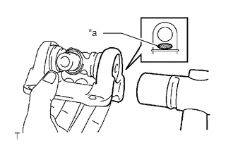
| *a | Hammering Point |
Using a hammer, tap the flange yoke until there is no clearance between the spider bearing outer race and snap ring.
- HINT:
-
Install the spider bearing on the sleeve side using the procedure described above.
Align the matchmarks on the flange yoke and propeller shaft.
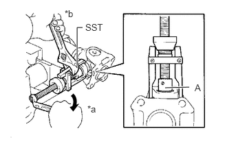
| *a | Turn |
| *b | Hold |
Using SST, install the 2 spider bearings to the spider.
- SST
- 09332-25010
- HINT:
-
Before installing SST, sufficiently raise the part labeled A. If the part labeled A is too low, it may be difficult to install SST.
Using SST, adjust both spider bearings so that the snap ring grooves are as wide as possible and equal in width.
- SST
- 09332-25010
Install 2 new snap rings to the installed spider bearings. The snap rings must have equal thickness and allow 0 to 0.05 mm (0 to 0.00196in.) of axial play.
- NOTICE:
-
While the installed snap rings should have equal thickness, if the axial play is greater than 0.05 mm (0.00196in.), select 2 snap rings that have as close to the same thickness as possible.
- HINT:
-
Do not reuse the snap rings.
| Part No. | Mark | Thickness |
|---|---|---|
| 90520-T0007 | F | 2.18 to 2.20 mm (0.0859 to 0.0866 in.) |
| 90520-T0008 | G | 2.20 to 2.22 mm (0.0867 to 0.0874 in.) |
| 90520-T0009 | H | 2.22 to 2.24 mm (0.0875 to 0.0881 in.) |
| 90520-T0010 | J | 2.24 to 2.26 mm (0.0882 to 0.0889 in.) |
| 90520-T0011 | K | 2.26 to 2.28 mm (0.0890 to 0.0897 in.) |
| 90520-T0012 | 1 | 2.28 to 2.30 mm (0.0898 to 0.0905 in.) |
| 90520-T0013 | 2 | 2.30 to 2.32 mm (0.0906 to 0.0913 in.) |
| 90520-T0014 | 3 | 2.32 to 2.34 mm (0.0914 to 0.0921 in.) |
| 90520-T0015 | 4 | 2.34 to 2.36 mm (0.0922 to 0.0929 in.) |
| 90520-T0016 | 5 | 2.36 to 2.38 mm (0.0930 to 0.0937 in.) |
| 90520-T0017 | 6 | 2.38 to 2.40 mm (0.0938 to 0.0944 in.) |
| 90520-T0018 | 7 | 2.40 to 2.42 mm (0.0945 to 0.0952 in.) |
| 90520-T0019 | 8 | 2.42 to 2.44 mm (0.0953 to 0.0960 in.) |
| 90520-T0020 | N | 2.44 to 2.46 mm (0.0961 to 0.0968 in.) |
| 90520-T0021 | 10 | 2.46 to 2.48 mm (0.0969 to 0.0976 in.) |
| 90520-T0022 | A | 2.48 to 2.50 mm (0.0977 to 0.0984 in.) |
| 90520-T0023 | B | 2.50 to 2.52 mm (0.0985 to 0.0992 in.) |
| 90520-T0024 | C | 2.52 to 2.54 mm (0.0993 to 0.0999 in.) |
| 90520-T0025 | D | 2.54 to 2.56 mm (0.1000 to 0.1007 in.) |
| 90520-T0026 | E | 2.56 to 2.58 mm (0.1008 to 0.1015 in.) |
- NOTICE:
- ·
Use a new snap ring.
·Use snap rings with as close to the same thickness as possible on both ends.
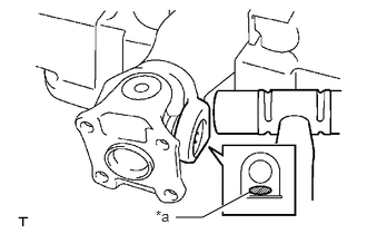
| *a | Hammering Point |
Using a hammer, tap the propeller shaft until there is no clearance between the spider bearing outer race and snap ring.
- HINT:
-
Install the spider bearing on the sleeve side using the procedure described above.
2.INSPECT PROPELLER SHAFT GREASE FITTING DIRECTION
- HINT:
- ·
When replacing a spider bearing, be sure that the grease fitting hole is facing the direction shown in the illustration.
·Fill the grease fittings with grease.
- Grease:
Lithium base chassis grease NLGI No. 2
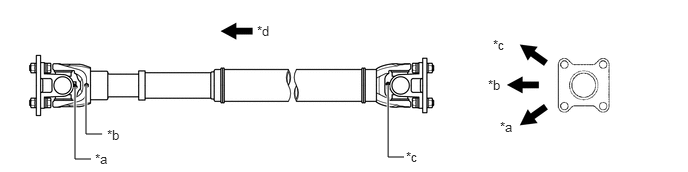
| *a | No. 1 Grease Fitting | *b | No. 2 Grease Fitting |
| *c | No. 3 Grease Fitting | *d | Vehicle Rear |
3.INSPECT SPIDER BEARING