Home › Engine / Hybrid System › 1GR-FE ENGINE CONTROL › SFI SYSTEM › from 2016.01
RM3270E _51 Engine / Hybrid System _048729 1GR-FE ENGINE CONTROL _0231393 SFI SYSTEM J

1GR-FE ENGINE CONTROL  SFI SYSTEM  Fuel Injector Circuit  


DESCRIPTION

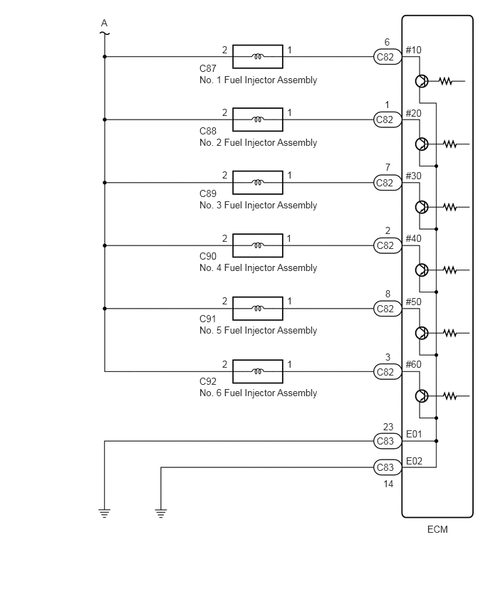
The fuel injector assemblies are located on the intake port. They inject fuel into the cylinders based on the signals from the ECM.

WIRING DIAGRAM
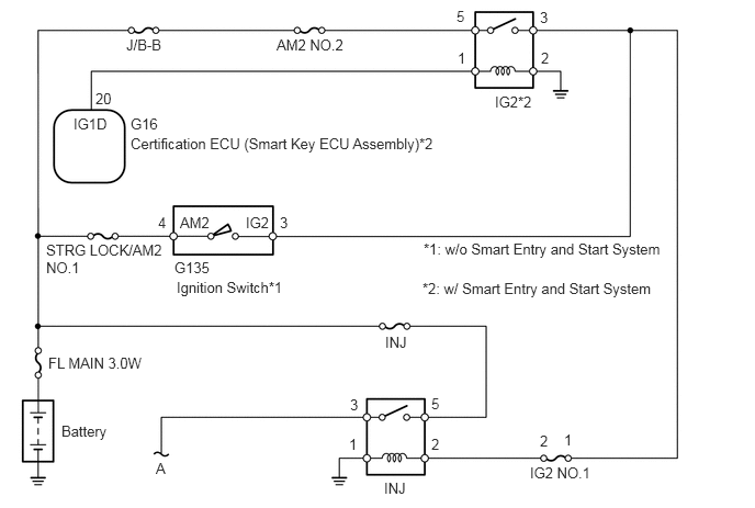
A353943E04
1.24,1.281 4.24,1.49 3,0.208 10 false Certification ECU (Smart Key ECU Assembly)*2 1.24,1.094 1.698,1.292 0.458,0.198 10 false G16 0.698,1.094 1.313,1.292 0.615,0.198 10 false IG1D 0.906,0.854 1.219,1.052 0.313,0.198 10 false 20 4.344,0.469 4.5,0.667 0.156,0.198 10 false 1 5.135,0.469 5.292,0.667 0.156,0.198 10 false 2 5.125,0.083 5.281,0.281 0.156,0.198 10 false 3 4.333,0.073 4.49,0.271 0.156,0.198 10 false 5 2.625,0.344 3.333,0.531 0.708,0.188 10 false AM2 NO.2 1.198,0.344 1.906,0.531 0.708,0.188 10 false J/B-B 4.698,0.885 5.156,1.083 0.458,0.198 10 false IG2*2 2.333,2.031 2.792,2.229 0.458,0.198 10 false IG2 1.708,2.031 2.167,2.229 0.458,0.198 10 false AM2 0.438,2.292 1.573,2.635 1.135,0.344 10 false STRG LOCK/AM2 NO.1 1.656,2.458 2.083,2.625 0.427,0.167 10 false G135 1.677,2.646 2.74,2.865 1.063,0.219 10 false Ignition Switch*1 0.458,3.365 2.292,3.563 1.833,0.198 10 false FL MAIN 3.0W 0.583,4.01 1.104,4.219 0.521,0.208 10 false Battery 1.479,4.365 1.635,4.563 0.156,0.198 10 false A 4.021,2.281 6.396,2.479 2.375,0.198 10 false *1: w/o Smart Entry and Start System 3.646,4.552 4.104,4.75 0.458,0.198 10 false INJ 3.656,3.167 4.115,3.365 0.458,0.198 10 false INJ 4.094,3.75 4.25,3.948 0.156,0.198 10 false 5 4.094,4.135 4.25,4.333 0.156,0.198 10 false 2 3.323,3.76 3.479,3.958 0.156,0.198 10 false 3 3.313,4.135 3.469,4.333 0.156,0.198 10 false 1 5.031,4.406 5.667,4.594 0.635,0.188 10 false IG2 NO.1 1.5,2.031 1.656,2.229 0.156,0.198 10 false 4 2.656,2.031 2.813,2.229 0.156,0.198 10 false 3 5.125,4.104 5.281,4.302 0.156,0.198 10 false 2 5.354,4.094 5.51,4.292 0.156,0.198 10 false 1 4.01,2.656 6.396,2.854 2.385,0.198 10 false *2: w/ Smart Entry and Start System

A375082E03
1.479,0.25 1.646,0.417 0.167,0.167 10 false A 3.25,0.646 3.417,0.813 0.167,0.167 10 false 2 4.198,0.646 4.365,0.813 0.167,0.167 10 false 1 2.917,0.917 3.333,1.083 0.417,0.167 10 false C87 2.917,1.083 4.75,1.333 1.833,0.25 10 false No. 1 Fuel Injector Assembly 2.917,1.833 3.25,2 0.333,0.167 10 false C88 2.917,2 4.75,2.25 1.833,0.25 10 false No. 2 Fuel Injector Assembly 2.917,2.75 3.25,2.917 0.333,0.167 10 false C89 2.917,2.917 4.75,3.167 1.833,0.25 10 false No. 3 Fuel Injector Assembly 2.917,3.667 3.25,3.833 0.333,0.167 10 false C90 2.917,3.833 4.75,4.083 1.833,0.25 10 false No. 4 Fuel Injector Assembly 2.917,4.583 3.333,4.75 0.417,0.167 10 false C91 2.917,4.75 4.75,5 1.833,0.25 10 false No. 5 Fuel Injector Assembly 2.917,5.5 3.333,5.667 0.417,0.167 10 false C92 2.917,5.667 4.75,5.917 1.833,0.25 10 false No. 6 Fuel Injector Assembly 5.625,0.531 5.792,0.698 0.167,0.167 10 false 6 5.51,0.75 5.927,0.917 0.417,0.167 10 false C82 5.625,1.448 5.792,1.615 0.167,0.167 10 false 1 5.635,2.365 5.802,2.531 0.167,0.167 10 false 7 5.635,3.292 5.802,3.458 0.167,0.167 10 false 2 5.635,4.219 5.802,4.417 0.167,0.198 10 false 8 5.635,5.146 5.802,5.313 0.167,0.167 10 false 3 5.604,6.167 5.854,6.333 0.25,0.167 10 false 23 5.51,6.375 5.927,6.542 0.417,0.167 10 false C83 5.604,7 5.854,7.167 0.25,0.167 10 false 14 5.938,0.646 6.271,0.813 0.333,0.167 10 false #10 5.938,1.573 6.271,1.74 0.333,0.167 10 false #20 5.938,2.49 6.271,2.656 0.333,0.167 10 false #30 5.938,3.406 6.271,3.573 0.333,0.167 10 false #40 5.938,4.333 6.271,4.5 0.333,0.167 10 false #50 5.938,5.25 6.25,5.417 0.313,0.167 10 false #60 5.938,6.271 6.354,6.438 0.417,0.167 10 false E01 5.938,6.667 6.271,6.833 0.333,0.167 10 false E02 6.25,7.667 6.667,7.833 0.417,0.167 10 false ECM 3.25,1.563 3.417,1.729 0.167,0.167 10 false 2 3.25,2.479 3.417,2.646 0.167,0.167 10 false 2 3.25,3.406 3.417,3.573 0.167,0.167 10 false 2 3.25,4.323 3.417,4.49 0.167,0.167 10 false 2 3.25,5.25 3.417,5.417 0.167,0.167 10 false 2 4.198,1.563 4.365,1.729 0.167,0.167 10 false 1 4.198,2.479 4.365,2.646 0.167,0.167 10 false 1 4.188,3.406 4.354,3.573 0.167,0.167 10 false 1 4.198,4.323 4.365,4.49 0.167,0.167 10 false 1 4.198,5.25 4.365,5.417 0.167,0.167 10 false 1 5.5,1.667 5.917,1.833 0.417,0.167 10 false C82 5.5,2.594 5.917,2.76 0.417,0.167 10 false C82 5.51,3.51 5.927,3.677 0.417,0.167 10 false C82 5.51,4.438 5.927,4.604 0.417,0.167 10 false C82 5.51,5.365 5.927,5.531 0.417,0.167 10 false C82 5.51,6.76 5.927,6.927 0.417,0.167 10 false C83

CAUTION / NOTICE / HINT

NOTICE:

Inspect the fuses for circuits related to this system before performing the following procedure.


PROCEDURE
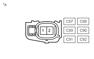
1.CHECK TERMINAL VOLTAGE (POWER SOURCE OF FUEL INJECTOR ASSEMBLY)
A201049C97
2.333,0.667 2.75,0.917 0.417,0.25 2.833,0.667 3.25,0.917 0.417,0.25 2.333,1 2.75,1.25 0.417,0.25 2.333,1.333 2.75,1.583 0.417,0.25 2.833,1 3.25,1.25 0.417,0.25 2.833,1.333 3.25,1.583 0.417,0.25 0.104,0.083 0.333,0.25 0.229,0.167 10 false *a 2.917,1.375 3.302,1.542 0.385,0.167 10 false C92 2.417,1.375 2.833,1.542 0.417,0.167 10 false C91 2.417,1.042 2.729,1.208 0.313,0.167 10 false C89 2.917,0.708 3.25,0.875 0.333,0.167 10 false C88 2.917,1.042 3.208,1.208 0.292,0.167 10 false C90 2.417,0.708 2.75,0.875 0.333,0.167 10 false C87
*a Front view of wire harness connector
(to Fuel Injector Assembly)


a.

Disconnect the fuel injector assembly connectors.


b.

Turn the ignition switch to ON.


c.

Measure the voltage according to the value(s) in the table below.

Standard Voltage:
Tester Connection Condition Specified Condition
C87-2 - Body ground Ignition switch ON 11 to 14 V
C88-2 - Body ground Ignition switch ON 11 to 14 V
C89-2 - Body ground Ignition switch ON 11 to 14 V
C90-2 - Body ground Ignition switch ON 11 to 14 V
C91-2 - Body ground Ignition switch ON 11 to 14 V
C92-2 - Body ground Ignition switch ON 11 to 14 V


Result:
Proceed to
OK
NG


OK

2.INSPECT FUEL INJECTOR ASSEMBLY

NG

4.CHECK HARNESS AND CONNECTOR (INJ RELAY - FUEL INJECTOR ASSEMBLY)
2.INSPECT FUEL INJECTOR ASSEMBLY
a.

Inspect the fuel injector assembly.

Click hereEngine / Hybrid System>1GR-FE FUEL>FUEL INJECTOR>INSPECTION

HINT:

Perform "Inspection After Repair" after replacing the fuel injector assembly.

Click hereEngine / Hybrid System>1GR-FE ENGINE CONTROL>SFI SYSTEM>INITIALIZATION


Result:
Proceed to
OK
NG


OK

3.CHECK HARNESS AND CONNECTOR (FUEL INJECTOR ASSEMBLY - ECM)

NG

REPLACE FUEL INJECTOR ASSEMBLY

3.CHECK HARNESS AND CONNECTOR (FUEL INJECTOR ASSEMBLY - ECM)
a.

Disconnect the fuel injector assembly connectors.


b.

Disconnect the ECM connector.


c.

Measure the resistance according to the value(s) in the table below.

Standard Resistance:
Tester Connection Condition Specified Condition
C87-1 - C82-6 (#10) Always Below 1 Ω
C88-1 - C82-1 (#20) Always Below 1 Ω
C89-1 - C82-7 (#30) Always Below 1 Ω
C90-1 - C82-2 (#40) Always Below 1 Ω
C91-1 - C82-8 (#50) Always Below 1 Ω
C92-1 - C82-3 (#60) Always Below 1 Ω
C87-1 or C82-6 (#10) - Body ground and other terminals Always 10 kΩ or higher
C88-1 or C82-1 (#20) - Body ground and other terminals Always 10 kΩ or higher
C89-1 or C82-7 (#30) - Body ground and other terminals Always 10 kΩ or higher
C90-1 or C82-2 (#40) - Body ground and other terminals Always 10 kΩ or higher
C91-1 or C82-8 (#50) - Body ground and other terminals Always 10 kΩ or higher
C92-1 or C82-3 (#60) - Body ground and other terminals Always 10 kΩ or higher


Result:
Proceed to
OK
NG


OK

PROCEED TO NEXT SUSPECTED AREA SHOWN IN PROBLEM SYMPTOMS TABLE

NG

REPAIR OR REPLACE HARNESS OR CONNECTOR

4.CHECK HARNESS AND CONNECTOR (INJ RELAY - FUEL INJECTOR ASSEMBLY)
a.

Remove the INJ relay from the engine room relay block and junction block assembly.


b.

Disconnect the fuel injector assembly connectors.


c.

Measure the resistance according to the value(s) in the table below.

Standard Resistance:
Tester Connection Condition Specified Condition
INJ relay terminal 3 - C87-2 Always Below 1 Ω
INJ relay terminal 3 - C88-2 Always Below 1 Ω
INJ relay terminal 3 - C89-2 Always Below 1 Ω
INJ relay terminal 3 - C90-2 Always Below 1 Ω
INJ relay terminal 3 - C91-2 Always Below 1 Ω
INJ relay terminal 3 - C92-2 Always Below 1 Ω
INJ relay terminal 3 or C87-2 - Body ground and other terminals Always 10 kΩ or higher
INJ relay terminal 3 or C88-2 - Body ground and other terminals Always 10 kΩ or higher
INJ relay terminal 3 or C89-2 - Body ground and other terminals Always 10 kΩ or higher
INJ relay terminal 3 or C90-2 - Body ground and other terminals Always 10 kΩ or higher
INJ relay terminal 3 or C91-2 - Body ground and other terminals Always 10 kΩ or higher
INJ relay terminal 3 or C92-2 - Body ground and other terminals Always 10 kΩ or higher


Result:
Proceed to
OK
NG


OK

NG

REPAIR OR REPLACE HARNESS OR CONNECTOR