A750F AUTOMATIC TRANSMISSION / TRANSAXLE TRANSMISSION CONTROL CABLE ADJUSTMENT
PROCEDURE

 1.SECURE VEHICLE
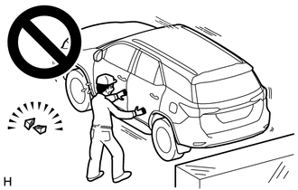
Fully apply the parking brake and chock a wheel.
- CAUTION:
-
- ·
Make sure to apply the parking brake and chock a wheel before performing this procedure.
·If the vehicle is not secure and the shift lever is moved to N, the vehicle may suddenly move, possibly resulting in an accident or serious injury.
2.INSPECT SHIFT LEVER POSITION
When moving the shift lever from P to R with the ignition switch ON and the brake pedal depressed, make sure that the shift lever moves smoothly and correctly into position.
Start the engine and make sure that the vehicle moves forward after moving the shift lever from N to D, and moves rearward after shifting to the R.
If the results are not as specified, inspect the park/neutral position switch and check the shift lever.
33820B
3.ADJUST TRANSMISSION CONTROL CABLE ASSEMBLY
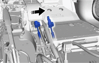
Move the shift lever to N.

|
Disconnect in this Direction |
Disconnect the end of the transmission control cable assembly from the transmission floor shift assembly.
| *1 | Lock Piece |
| *a | Side View |
| *b | Bottom View |
| *c | Push |
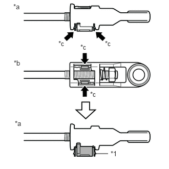
Push the 2 claws together at the top of the transmission control cable lock piece. While holding the 2 claws together, push the 2 lugs on the bottom of the lock piece toward each other and upward to pull out the lock piece.
| *1 | Lock Piece |
|
|
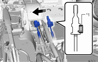
Connect in this Direction |
Connect the end of the transmission control cable assembly to the transmission floor shift assembly.
- NOTICE:
- ·
The shift lever should be in N.
·Make sure that the lock piece is pulled up.
·Push on the end of the cable all the way to the base of the transmission floor shift assembly pin.
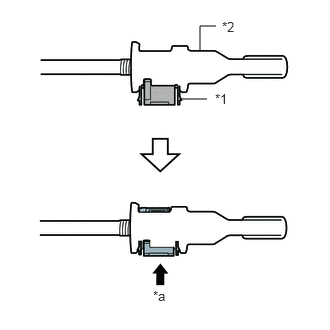
| *1 | Lock Piece |
| *2 | Adjuster Case |
| *a | Push |
Push the lock piece into the adjuster case.
- NOTICE:
- ·
Check that the park/neutral position switch assembly and shift lever are in neutral.
·Securely push in the lock piece until it locks.
4.ADJUST SHIFT LEVER POSITION
Move the shift lever to N.
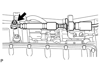
Remove the nut and disconnect the transmission control cable assembly.
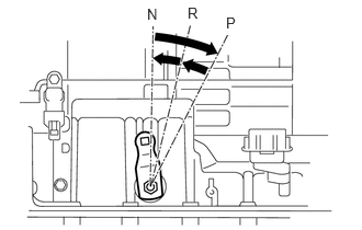
Turn the control shaft lever clockwise until it stops, and then turn it counterclockwise 2 notches to set it to the N position.
While holding the control shaft lever slightly toward the R position side, connect the transmission control cable assembly with the nut.
- Torque:
- 14 N*m (143 kgf*cm, 10 ft.*lbf)