5L-E ENGINE CONTROL ECD SYSTEM Air Conditioning Signal Circuit
DESCRIPTION
When the A/C compressor is on, the A/C amplifier sends the A/C signal to the ECM and the ECM increases the fuel injection volume to improve driveability during engine idling.
WIRING DIAGRAM
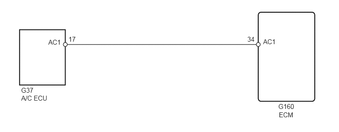
PROCEDURE
Connect the GTS to the DLC3.
Start the engine and turn the air conditioning switch on.
- HINT:
-
The A/C magnetic clutch is turned on.
Enter the following menus: Powertrain / Engine and ECT / Active Test / Control the A/C Cut Signal
- Powertrain > Engine and ECT > Active Test
-
Tester Display Control the A/C Cut Signal - 50004 61 48
Check operation of the A/C magnetic clutch cut when air conditioning cut control is operated by the GTS.
- OK:
A/C magnetic clutch is turned off.
- Result:
Proceed to OK NG
OK
NG
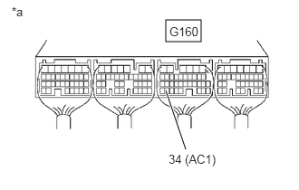
| *a | Component with harness connected
(ECM) |
Start the engine.
Measure the voltage according to the value(s) in the table below.
- Standard voltage:
Tester Connection Switch Condition Specified Condition G160-34 (AC1) - Body ground Engine idling 11 to 14 V G160-34 (AC1) - Body ground Ignition switch ON, engine stopped 0 to 3 V
- Result:
Proceed to OK NG
OK
NG
Disconnect the A/C amplifier connector.
Disconnect the ECM connector.
Measure the resistance according to the value(s) in the table below.
- Standard resistance:
Tester Connection Condition Specified Condition G37-17 (AC1) - G160-34 (AC1) Always Below 1 Ω G37-17 (AC1) or G160-34 (AC1) - Body ground and other terminals Always 10 kΩ or higher
- Result:
Proceed to OK NG
OK
NG