5L-E ENGINE CONTROL ECD SYSTEM TERMINALS OF ECM
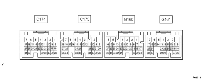
- HINT:
-
Each ECM terminal's standard voltage is shown in the table below.
-
In the table, first follow the information under "Condition".
-
Look under "Terminal No. (Symbol)" for the terminals to be inspected. The standard voltage between the terminals is shown under "Specified Condition".
-
Use the illustration above as a reference for the ECM terminals.
| Terminal No. (Symbol) | Wiring Color | Terminal Description | Condition | Specified Condition |
|---|---|---|---|---|
| G161-2 (BATT) - C174-5 (E1) | Y - BR | Battery (for measuring the battery voltage and for the ECM memory) | Always | 11 to 14 V |
| G161-8 (SREL) - C174-5(E1) | LG - BR | GLOW relay | Cranking | 11 to 14 V |
| Idling (engine started and 600 sec. have passed) | 0 to 1.5 V | |||
| G161-10 (MREL) - C174-5(E1) | G - BR | MAIN relay | Ignition switch ON | 11 to 14 V |
| Ignition switch off (2 sec. after ignition switch off) | 0 to 1.5 V | |||
| G161-17 (TC) - C174-5 (E1) | R - BR | Terminal TC of DLC3 | Ignition switch ON | 11 to 14 V |
| G160-25 (SP1) - C174-5 (E1) | V- -BR | Speed signal from combination meter | Ignition switch ON, slowlyrotate wheel | Pulse generation
(See waveform 1) |
| G160-6 (STA) - C174-5 (E1) | GR - BR | Starter signal | Cranking | 6 V or more |
| G161-1 (+B) - C174-5 (E1) | L - BR | Power source of ECM | Ignition switch ON | 11 to 14 V |
| G161-11 (IGSW) - C174-5(E1) | GR - BR | Ignition switch | Ignition switch ON | 11 to 14 V |
| G160-9 (STP) - C174-5 (E1) | L - BR | Stop light switch | Brake pedal depressed | 11 to 14 V |
| Brake pedal released | Below 1.5 V | |||
| G160-34(AC1) - C174-5 (E1) | GR - BR | A/C amplifier | A/C switch on
(magnetic clutch on) |
Below 1.5 V |
| A/C switch off | 7.5 to 14 V | |||
| G161-9 (ACT) - C174-5 (E1) | LG - BR | A/C amplifier | Ignition switch ON | 11 to 14 V |
| A/C cut performed (driving below 30 km/h (18.6 mph), accelerator pedal fully depressed for 5 sec.) | 0 to 3 V | |||
| G161-20 (VPA) - G161-27(EPA) | W - G | Accelerator pedal position sensor (for engine control) | Ignition switch ON, accelerator pedal released | 0.6 to 1.0 V |
| Ignition switch ON, accelerator pedal depressed | 3.0 to 4.6 V | |||
| G161-28 (VPA2) - G161-29(EPA2) | GR - Y | Accelerator pedal position sensor (for sensor malfunction detection) | Ignition switch ON, accelerator pedal released | 1.4 to 1.8 V |
| Ignition switch ON, accelerator pedal depressed | 3.7 to 5.0 V | |||
| G161-26 (VCPA) - G161-27(EPA) | LG - G | Power source of accelerator pedal position sensor (for VPA) | Ignition switch ON | 4.5 to 5.0 V |
| G161-23 (VCP2) - G161-29(EPA2) | R - Y | Power source of accelerator pedal position sensor (for VPA2) | Ignition switch ON | 4.5 to 5.0 V |
| G160-7 (TACH) - C174-5(E1) | V - BR | Engine speed sensor | Idling | Pulse generation
(See waveform 2) |
| G160-10 (ST1-) - C174-5(E1) | GR - BR | Stop light switch | Brake pedal depressed | 0 to 1.5 V |
| Brake pedal released | 7.5 to 14 V | |||
| C175-33 (PIM) - C175-32(EPIM) | L - GR | Manifold absolute pressure sensor | 60 kPa (450 mmHg, 17.7 in.Hg) vacuum applied | 0.2 to 0.8 V |
| 207 kPa (1550 mmHg, 61.0 in.Hg) vacuum applied | 4.2 to 4.8 V | |||
| C175-22 (THA) - C175-30(ETHA) | Y - R | Intake air temperaturesensor | Idling, air intake temp. 0°C (32°F) to 80°C (176°F) | 0.5 to 3.4 V |
| C175-21 (THW) - C175-29(ETHW) | R - B | Engine coolant temperature sensor | Idling, engine coolant temp. 60°C (140°F) to 120°C (248°F) | 0.2 to 1.0 V |
| C175-23 (THF) - C175-31(ETHF) | G - R | Terminal TC of DLC3 | Ignition switch ON | 11 to 14 V |
| C174-29 (DATA) - C174-5(E1) | Y - BR | Injection pump | Within 0.5 sec. after ignition switch ON | Pulse generation |
| C174-28 (CLK) - C174-5 (E1) | L - BR | Injection pump | Within 0.5 sec. after ignition switch ON | Pulse generation |
| C175-15 (THOP) - C174-5(E1) | GR - BR | Throttle open switch | Idling (engine warmed up) | 11 to 14 V |
| Ignition switch ON (once within 5 sec.) | 0 to 3 V | |||
| C174-14 (LU-B) - C174-7(E01) | Y - W-B | Throttle control motor
(intake shutter) |
Racing (engine warmed up) | Pulse generation
(See waveform 3) |
| C174-15 (LU+B) - C174-7(E01) | R - W-B | Throttle control motor
(intake shutter) |
Racing (engine warmed up) | Pulse generation
(See waveform 3) |
| C174-16 (LU-A) - C174-7(E01) | W - W-B | Throttle control motor
(intake shutter) |
Racing (engine warmed up) | Pulse generation
(See waveform 3) |
| C174-17 (LU+A) - C174-7(E01) | GR - W-B | Throttle control motor
(intake shutter) |
Racing (engine warmed up) | Pulse generation
(See waveform 3) |
| C174-11 (TCV) - C174-7(E01) | R - W-B | Timing control valve | Ignition switch ON | 11 to 14 V |
| Idling | Pulse generation
(See waveform 4) |
|||
| C174-2 (SPV+) - C174-5 (E1) | L - BR | Spill control valve | Ignition switch ON | 11 to 14 V |
| Idling | Pulse generation | |||
| C174-1 (SPV-) - C174-5 (E1) | Y - BR | Spill control valve | Idling | Pulse generation
(See waveform 5) |
| C175-26 (TDC+) - C175-34(TDC-) | R - G | Crankshaft position sensor | Idling | Pulse generation
(See waveform 6) |
| C175-27 (NE+) - C175-35(NE-) | L - Y | Engine speed sensor | Idling | Pulse generation
(See waveform 6) |
| G161-25 (CANH) - C174-5(E1) | B - BR | CAN communication line | Ignition switch ON | Pulse generation
(See waveform 7) |
| G161-31 (CANL) - C174-5(E1) | W - BR | CAN communication line | Ignition switch ON | Pulse generation
(See waveform 8) |
Waveform 1
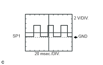
Speed signal
| ECM TerminalName | Between SP1 and E1 |
| Tester Range | 2 V/DIV., 20 msec./DIV. |
| Condition | Driving at approx. 20 km/h (12.4 mph) |
- HINT:
- ·
As vehicle speed increases, the wavelength becomes shorter.
·As vehicle speed increases, the waveform's amplitude becomes greater.
Waveform 2
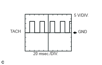
Engine speed signal
| ECM TerminalName | Between TACH and E1 |
| Tester Range | 5 V/DIV., 20 msec./DIV. |
| Condition | Idling after warming up |
- HINT:
-
As engine speed increases, the wavelength becomes shorter.
Waveform 3
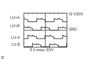
Throttle control motor signals
| ECM TerminalName | Between LU+A and E01
Between LU-A and E01 Between LU+B and E01 Between LU-B and E01 |
| Tester Range | 10 V/DIV., 0.5 msec./DIV. |
| Condition | Engine racing |
Waveform 4
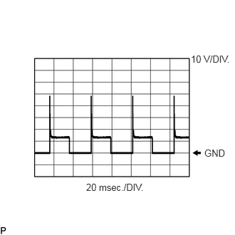
Timing control value signal
| ECM TerminalName | Between TCV and E01 |
| Tester Range | 10 V/DIV., 20 msec./DIV. |
| Condition | During idling |
Waveform 5
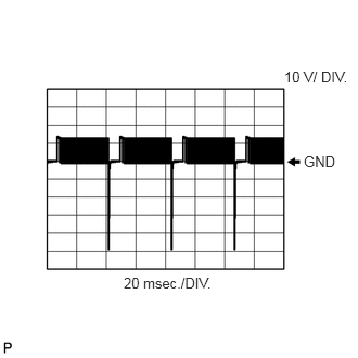
Spill control valve signal
| ECM TerminalName | Between SPV- and E1 |
| Tester Range | 10 V/DIV., 20 msec./DIV. |
| Condition | During idling |
Waveform 6
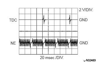
Crankshaft position sensor and engine speed sensor signals
| ECM TerminalName | Between TDC+ and TDC-
Between NE+ and NE- |
| Tester Range | 2 V/DIV., 20 msec./DIV. |
| Condition | During idling |
Waveform 7
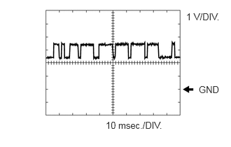
CAN Communication Signal
| ECM TerminalName | Between CANH and E1 |
| Tester Range | 1 V/DIV., 10 msec./DIV. |
| Condition | Engine stopped, ignition switch ON |
- HINT:
-
The waveform varies depending on the CAN communication signal.
Waveform 8
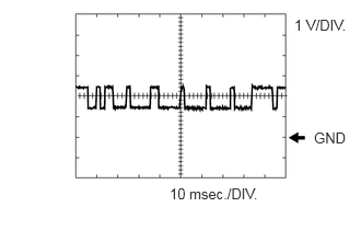
CAN Communication Signal
| ECM TerminalName | Between CANL and E1 |
| Tester Range | 1 V/DIV., 10 msec./DIV. |
| Condition | Engine stopped, ignition switch ON |
- HINT:
-
The waveform varies depending on the CAN communication signal.