2TR-FE ENGINE MECHANICAL ENGINE UNIT REMOVAL
CAUTION / NOTICE / HINT
The necessary procedures (adjustment, calibration, initialization, or registration) that must be performed after parts are removed, installed, or replaced during the engine unit removal/installation are shown below.
| Replacement Part or Procedure | Necessary Procedures | Effects/Inoperative when not Performed | Link |
|---|---|---|---|
·
Replacement of throttle with motor body assembly ·
Cleaning the deposits from the throttle with motor body assembly ·
Replacement of cylinder head sub-assembly ·
Replacement of camshaft (for intake or exhaust camshaft) ·
Replacement of camshaft timing gear assembly ·
Replacement of camshaft timing exhaust gear assembly ·
Replacement of fuel injector assembly ·
Replacement of engine coolant temperature sensor ·
Replacement of spark plug ·
Replacement of ignition coil assembly ·
Replacement of knock sensor |
Inspection after repair | Poor idle, engine start, etc. | ( ) |
PROCEDURE

 22030
1.REMOVE THROTTLE BODY WITH MOTOR ASSEMBLY
23250
2.REMOVE FUEL DELIVERY PIPE WITH FUEL INJECTOR
17650G
3.REMOVE PURGE VSV
12229
4.REMOVE PCV PIPE
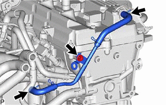
Disconnect the PCV hose from the PCV valve sub-assembly and intake manifold.
Remove the bolt and PCV pipe.
17111
5.REMOVE INTAKE MANIFOLD
6.REMOVE ENGINE WIRE
Disconnect the connectors and clamps of the engine wire connected to the engine assembly.
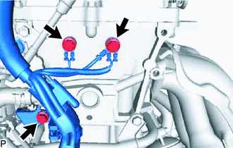
Remove the 3 bolts and engine wire from the engine assembly.
7.REMOVE HEATER HOSE (w/ Heater)
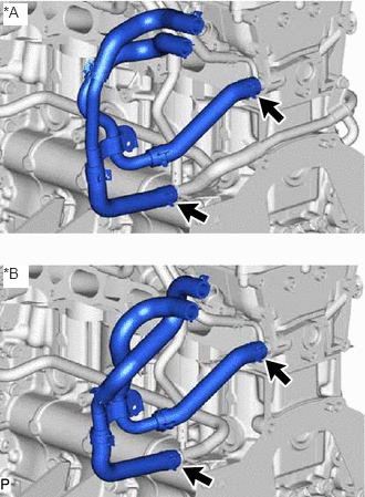
| *A | for LHD |
| *B | for RHD |
Slide the 2 clamp and remove the heater hose from the cylinder head sub-assembly and No. 1 water by-pass pipe.
8.REMOVE HOSE PLUG (w/o Heater)
Slide the 2 clamps and remove the 2 hose plugs from the cylinder head sub-assembly.
16261G
9.REMOVE NO. 1 WATER BY-PASS HOSE (w/ Heater)
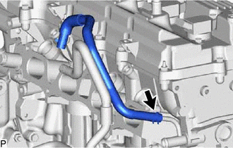
Slide the clamp and remove the No. 1 water by-pass hose from the cylinder head sub-assembly.
12315
10.REMOVE FRONT NO. 1 ENGINE MOUNTING BRACKET LH
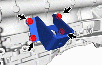
Remove the 4 bolts and front No. 1 engine mounting bracket LH.
12311
11.REMOVE FRONT NO. 1 ENGINE MOUNTING BRACKET RH
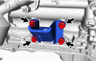
Remove the 4 bolts and front No. 1 engine mounting bracket RH.
17167
12.REMOVE NO. 1 EXHAUST MANIFOLD HEAT INSULATOR (w/o Secondary Air Injection System)
17167
13.REMOVE NO. 1 EXHAUST MANIFOLD HEAT INSULATOR (w/ Secondary Air Injection System)
17117B
14.REMOVE NO. 4 INTAKE PIPE (w/ Secondary Air Injection System)
25710
15.REMOVE AIR SWITCHING VALVE ASSEMBLY (w/ Secondary Air Injection System)
17141
16.REMOVE EXHAUST MANIFOLD
19500
17.REMOVE IGNITION COIL ASSEMBLY
27020
18.REMOVE GENERATOR ASSEMBLY
for 80A Type:
Click herePower Source / Network>2TR-FE BATTERY / CHARGING>GENERATOR(for 80A Type)>REMOVAL
for 100A Type:
Click herePower Source / Network>2TR-FE BATTERY / CHARGING>GENERATOR(for 100A Type)>REMOVAL
for 115A Type:
Click herePower Source / Network>2TR-FE BATTERY / CHARGING>GENERATOR(for 115A Type)>REMOVAL
88440B
19.REMOVE IDLE PULLEY ASSEMBLY
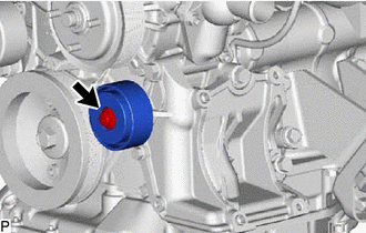
Loosen the bolt and then remove the idle pulley assembly.
- HINT:
-
The bolt in the illustration cannot be removed from the idle pulley assembly.
88431
20.REMOVE NO. 1 COMPRESSOR MOUNTING BRACKET
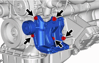
Remove the 5 bolts and No. 1 compressor mounting bracket.
16603
21.REMOVE NO. 1 IDLER PULLEY SUB-ASSEMBLY
16268
22.REMOVE NO. 1 WATER BY-PASS PIPE (w/ Heater)
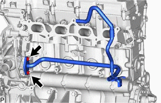
Remove the 2 nuts, No. 1 water by-pass pipe and gasket.
16353A
23.REMOVE WATER BY-PASS FLANGE (w/o Heater)
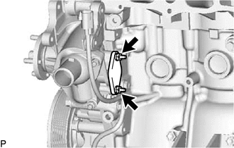
Remove the 2 nuts, water by-pass flange and gasket.