RM3270E
_58
Vehicle Interior
_041713
HEATING / AIR CONDITIONING
_0242480
AIR CONDITIONING SYSTEM(for Manual Cooler System)
D
HEATING / AIR CONDITIONING AIR CONDITIONING SYSTEM(for Manual Cooler System) SYSTEM DESCRIPTION
MODE POSITION AND DAMPER OPERATION
2.292,1.667 2.167,1.333
2.167,1.333 1.917,1.333
true
0.292,2.552 0.708,2.552
true
0.292,2.99 0.708,2.99
true
2.104,3.5 1.938,3.917
1.938,3.917 1.688,3.917
true
0.948,3.625 0.781,4.042
0.781,4.042 0.531,4.042
true
3.802,2.698 4.135,2.448
4.135,2.448 4.385,2.448
true
3.781,1.885 4.198,1.885
true
3.615,1.719 3.573,1.135
3.573,1.135 3.323,1.135
true
2.417,0.333 2.729,0.531
0.313,0.198
10
false
*1
0.844,0.417 1.156,0.615
0.313,0.198
10
false
*2
3.969,0.417 4.281,0.615
0.313,0.198
10
false
*3
0.135,2.104 0.448,2.302
0.313,0.198
10
false
*a
1.573,2.104 1.885,2.302
0.313,0.198
10
false
*b
1.75,1.26 2.063,1.458
0.313,0.198
10
false
*4
0.104,2.469 0.417,2.667
0.313,0.198
10
false
*5
0.125,2.896 0.438,3.094
0.313,0.198
10
false
*6
1.521,3.844 1.833,4.042
0.313,0.198
10
false
*8
0.354,3.958 0.667,4.156
0.313,0.198
10
false
*7
4.438,2.344 4.75,2.542
0.313,0.198
10
false
*9
4.229,1.792 4.542,1.99
0.313,0.198
10
false
*10
3.104,1.052 3.417,1.25
0.313,0.198
10
false
*11
3.958,4.854 4.271,5.052
0.313,0.198
10
false
*12
4.823,4.854 5.135,5.052
0.313,0.198
10
false
*13
5.917,5.094 6.229,5.292
0.313,0.198
10
false
*15
5.167,5.115 5.479,5.313
0.313,0.198
10
false
*14
6.667,5.083 6.979,5.281
0.313,0.198
10
false
*16
0.104,5.521 0.417,5.719
0.313,0.198
10
false
*c
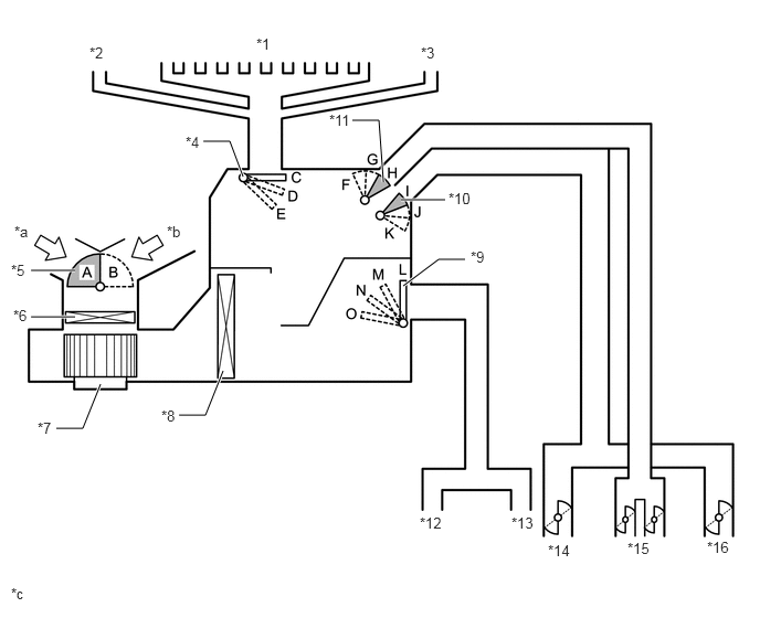
| *1 | Front Defroster | *2 | Side Defroster (LH) |
| *3 | Side Defroster (RH) | *4 | Mode Switching Damper (for Defroster) |
| *5 | No. 1 Blower Damper Servo Sub-assembly
- Fresh/Recirculation |
*6 | Clean Air Filter (Air Refiner Element) |
| *7 | Blower with Fan Motor Sub-assembly | *8 | No. 1 Cooler Evaporator |
| *9 | Mode Switching Damper (for Footwell Duct) | *10 | Mode Switching Damper (for Side Register) |
| *11 | Mode Switching Damper (for Center Register) | *12 | Footwell Duct (LH) |
| *13 | Footwell Duct (RH) | *14 | Side Register (LH) |
| *15 | Center Register | *16 | Side Register (RH) |
| *a | Recirculated Air | *b | Fresh Air |
| *c | This illustration shows the dampers and air outlets schematically. Shapes and numbers of parts shown in the illustration will differ from the actual. | - | - |
| Damper | Operation Position | Damper Position | Operation |
|---|---|---|---|
| Air Inlet Control Damper | FRESH | A | Brings in fresh air. |
| RECIRC | B | Recirculates internal air. | |
| Mode Control Damper | FACE | C, F, K, L | Air blows out of the center register and side register. |
| BI-LEVEL | C, G, J, N | Air blows out of the center register, side register and footwell register. | |
| FOOT | D, H, I, O | Air blows out of the footwell register duct. A small amount of air also blows out from the side register, front defroster and side defroster. | |
| FOOT/DEF | E, H, I, M | Defrosts the windshield through the front defroster and side defroster. At the same time, air is blown out from the footwell register. A small amount of air also blows out from the side register. | |
| DEF | E, H, I, L | Defrosts the windshield through the front defroster and side defroster. A small amount of air also blows out from the side register. |
AIR OUTLETS AND AIR FLOW VOLUME
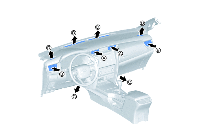
| Indication | Mode | Center Register | Side Register | Footwell Duct | Front Defroster, Side Defroster |
|---|---|---|---|---|---|
| A | B | C | D | ||

|
FACE | 
|
|
- | - |

|
BI-LEVEL | 
|
|
|
- |

|
FOOT | - | 
|
|
|

|
FOOT/DEF | - |
|
|
|

|
DEF | - |
|
- |
|
- HINT:
-
The circle size (○) is proportional to the amount of air flow.