Home › Engine / Hybrid System › 2TR-FE ENGINE CONTROL › SFI SYSTEM
NM1880E _51 Engine / Hybrid System _015470 2TR-FE ENGINE CONTROL _0076894 SFI SYSTEM DE DETAILS F

2TR-FE ENGINE CONTROL  SFI SYSTEM  DETAILS  VVT-i CONTROL  


OPERATION


a.

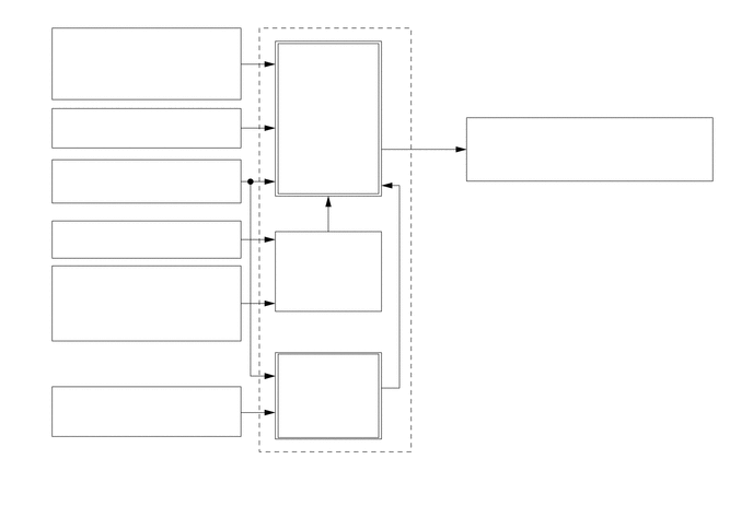
Using the engine speed, intake air mass, throttle position and engine coolant temperature, the ECM can calculate optimal valve timing for each driving condition and controls the camshaft timing oil control valve assembly. In addition, the ECM uses signals from the camshaft position sensor and the crankshaft position sensor to detect the actual valve timing, thus providing feedback control to achieve the target valve timing.
W104268
4.01,1.417 4.219,2.135 4.219,2.135 4.396,2.135 true 2.74,0.802 3.594,1.5 0.854,0.698 10 false Target Valve Timing 0.74,0.292 2.125,0.938 1.385,0.646 10 false Intake Mass Air Flow Meter Sub-assembly 0.646,1.063 2.188,1.417 1.542,0.354 10 false Throttle Position Sensor 0.542,1.552 2.271,1.906 1.729,0.354 10 false Crankshaft Position Sensor 0.583,3.719 2.313,4.073 1.729,0.354 10 false Camshaft Position Sensor 0.74,2.125 2.125,2.479 1.385,0.354 10 false Vehicle Speed Signal 0.76,2.563 2.01,3.271 1.25,0.708 10 false Engine Coolant Temperature Sensor 2.813,2.313 3.531,2.667 0.719,0.354 10 false Correction 3.156,3.031 3.833,3.365 0.677,0.333 10 false Feedback 2.74,3.438 3.542,4.125 0.802,0.688 10 false Actual Valve Timing 4.552,1.135 6.656,1.74 2.104,0.604 10 false Camshaft Timing Oil Control Valve Assembly 4.469,2.042 5.656,2.365 1.188,0.323 10 false Duty Cycle Control 3.021,4.365 3.385,4.604 0.365,0.24 10 false ECM


b.

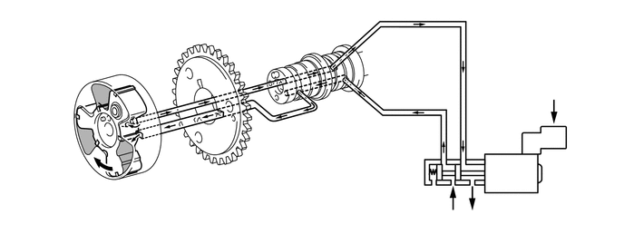
When the camshaft timing oil control valve assembly is positioned as illustrated below by the advance signals from the ECM, the resultant oil pressure is applied to the timing advance side vane chamber to rotate the camshaft in the timing advance direction:
W102423
0.927,1.323 0.646,0.521 0.646,0.521 0.938,0.521 true 1.177,1.938 1.177,2.5 1.177,2.5 1.396,2.5 true 5.198,2.333 5.031,2.479 5.031,2.479 4.896,2.479 true 5.427,2.219 5.635,2.385 5.635,2.385 5.802,2.385 true 0.99,0.458 1.177,0.74 0.188,0.281 10 false *1 1.438,2.406 1.625,2.688 0.188,0.281 10 false *a 6.302,0.958 6.531,1.198 0.229,0.24 10 false *2 4.729,2.365 4.958,2.604 0.229,0.24 10 false *b 5.844,2.313 6.073,2.552 0.229,0.24 10 false *c 0.083,0.063 0.396,0.26 0.313,0.198 10 false *A
*A Advance Side Operation - -
*1 Vane *2 ECM
*a Rotation Direction *b In (Oil Pressure)
*c Drain (Oil Pressure) - -


c.

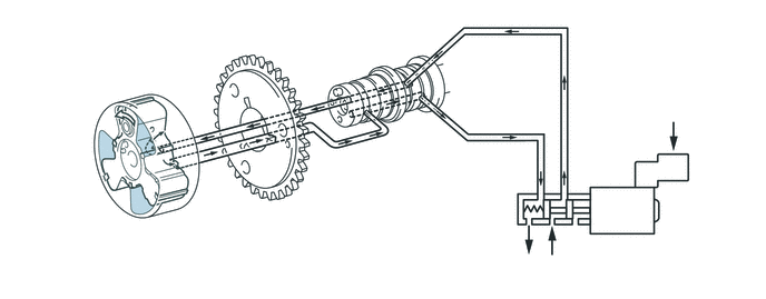
When the camshaft timing oil control valve assembly is positioned as illustrated below by the retard signals from the ECM, the resultant oil pressure is applied to the timing retard side vane chamber to rotate the camshaft in the timing retard direction:
W102965
1.125,1.052 1.125,0.656 1.125,0.656 0.938,0.656 true 4.938,2.198 4.667,2.354 4.667,2.354 4.531,2.354 true 5.167,2.281 5.354,2.396 5.354,2.396 5.5,2.396 true 1.063,1.667 0.927,2.01 0.927,2.01 0.792,2.01 true 0.635,1.917 0.875,2.135 0.24,0.219 10 false *1 0.76,0.552 1,0.771 0.24,0.219 10 false *a 4.344,2.25 4.583,2.469 0.24,0.219 10 false *b 5.531,2.302 5.771,2.521 0.24,0.219 10 false *c 6.208,0.917 6.448,1.135 0.24,0.219 10 false *2 0.115,0.073 0.427,0.271 0.313,0.198 10 false *A
*A Retard Side Operation - -
*1 Vane *2 ECM
*a Rotation Direction *b Drain (Oil Pressure)
*c In (Oil Pressure) - -


d.

After reaching the target timing, the valve timing is held by keeping the camshaft timing oil control valve assembly in the neutral position unless the traveling state changes. This adjusts the valve timing at the desired target position and prevents the engine oil from running out when it is unnecessary.