SUPPLEMENTAL RESTRAINT SYSTEMS AIRBAG SYSTEM CONTROL AIRBAG CONTROL
FUNCTION OF MAIN COMPONENTS
The main components in the airbag system have the following functions:
| Component | Function |
|---|---|
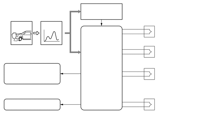
| Center Airbag Sensor Assembly | The center airbag sensor assembly receives signals from the deceleration sensor, the safing sensor built into the center airbag sensor assembly and one of the front airbag sensors, determines whether the driver airbag and front passenger airbag assembly should be activated, and diagnoses system malfunctions. |
| Steering Pad (Driver Side Squib) | These consist of an inflator, a bag, and so on. The inflator deploys gas in accordance with an expansion signal from the center airbag sensor assembly and deploys the bag. |
| Front Passenger Airbag Assembly | |
| Front Airbag Sensor | The front airbag sensor uses an electrical type deceleration sensor. Based on the deceleration of the vehicle during a frontal collision, a distortion is created in the sensor and converted into an electrical signal. Accordingly, the extent of the initial collision can be detected in detail. |
| Combination Meter Assembly
- SRS Warning Light |
The SRS warning light turns on to alert the driver when the center airbag sensor assembly detects a malfunction in the airbag system. |
OPERATING CONDITION
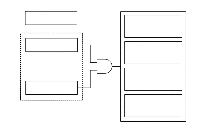
If the impact of a collision is greater than the specified value, the SRS is activated automatically. The center airbag sensor assembly includes the safing sensor and deceleration sensor. The safing sensor is designed to turn on at a lower deceleration rate than the deceleration sensor.
In case of a frontal collision, the center airbag sensor assembly determines whether airbag deployment is necessary based on signals from the deceleration sensor and the front airbag sensor. If the safing sensor turns on simultaneously, current flows to the squibs to deploy the SRS components as shown in the illustration below. However, a deployment ignition signal may be output with the deceleration sensor on signal even without a signal from a front airbag sensor.
SYSTEM CONTROL
Airbag for Frontal Collision
There are 2 types of airbags for frontal collisions: steering pad (driver side squib) and front passenger airbag assembly. These airbags deploy simultaneously.
DIAGNOSIS
If the center airbag sensor assembly detects a malfunction in the SRS airbag system, the center airbag sensor assembly stores the malfunction data in memory, in addition to illuminating the SRS warning light.
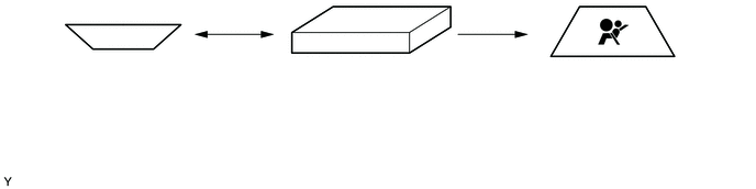
The center airbag sensor assembly outputs the malfunction data as 5-digit Diagnostic Trouble Codes (DTCs) to an intelligent tester II or the SRS warning light.
SRS Airbag System DTCs
The 5-digit DTCs can be read after connecting an intelligent tester II to the DLC3.
If the SRS airbag deploys, the center airbag sensor assembly will turn on the SRS warning light. However, in contrast to the ordinary diagnosis function, a DTC will not be stored. The SRS warning light cannot be turned off. It is necessary to replace the center airbag sensor assembly with a new one.