2TR-FE ENGINE MECHANICAL ENGINE UNIT INSTALLATION
PROCEDURE

 1.INSTALL FRONT NO. 1 ENGINE MOUNTING BRACKET RH
Install the engine mounting bracket with the 4 bolts.
- Torque:
- 51 N*m (520 kgf*cm, 38 ft.*lbf)
2.INSTALL FRONT NO. 1 ENGINE MOUNTING BRACKET LH
Install the engine mounting bracket with the 4 bolts.
- Torque:
- 51 N*m (520 kgf*cm, 38 ft.*lbf)
3.INSTALL NO. 1 WATER BY-PASS PIPE
Install a new gasket and the water by-pass pipe with the 2 nuts.
- Torque:
- 18 N*m (178 kgf*cm, 13 ft.*lbf)
4.INSTALL HEATER WATER OUTLET HOSE
5.INSTALL HEATER WATER INLET HOSE
6.INSTALL NO. 1 IDLER PULLEY SUB-ASSEMBLY
7.INSTALL NO. 1 COMPRESSOR MOUNTING BRACKET
- NOTICE:
-
Install the No. 1 compressor mounting bracket exactly as described in the procedures below to properly secure and prevent damage to the fan and generator V belt.
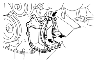
Temporarily install the No. 1 compressor mounting bracket with the 3 bolts.
- HINT:
-
Temporarily install the No. 1 compressor mounting bracket with the 3 bolts so that the bracket can be moved by hand.
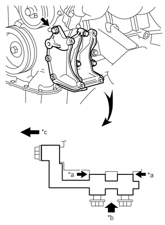
| *a | No Clearance |
| *b | Push |
| *c | Front |
Push the No. 1 compressor mounting bracket toward the cylinder block as shown in the illustration and tighten bolt B.
- Torque:
- for bolt B : 45 N*m (459 kgf*cm, 33 ft.*lbf)
- HINT:
-
Make sure there is no clearance between the cylinder block and No. 1 compressor mounting bracket as shown in the illustration.
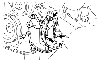

|
Bolt A |

|
Bolt C |
Uniformly tighten the 4 bolts in the order shown in the illustration.
- Torque:
- for bolt A : 45 N*m (459 kgf*cm, 33 ft.*lbf)
- for bolt C : 25 N*m (250 kgf*cm, 18 ft.*lbf)
8.INSTALL IDLE PULLEY ASSEMBLY
Temporarily install the idle pulley assembly with the bolt.
- NOTICE:
-
Do not use any tools.
Tighten the bolt.
- Torque:
- 44 N*m (449 kgf*cm, 32 ft.*lbf)
9.INSTALL EXHAUST MANIFOLD
10.INSTALL NO. 1 EXHAUST MANIFOLD HEAT INSULATOR
11.INSTALL INTAKE MANIFOLD
Install a new gasket.
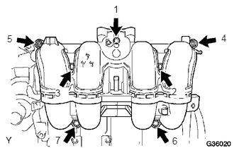
Install the intake manifold with the 5 bolts and 2 nuts and tighten the bolts and nuts in the order shown in the illustration.
- Torque:
- 25 N*m (255 kgf*cm, 18 ft.*lbf)
Connect the crankshaft position sensor to the clamp.
12.INSTALL PURGE VSV
13.INSTALL FUEL DELIVERY PIPE WITH FUEL INJECTOR
14.INSTALL THROTTLE BODY WITH MOTOR ASSEMBLY
15.INSTALL ENGINE WIRE
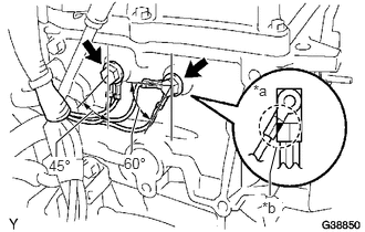
| *a | INCORRECT |
| *b | Do not Allow Wires to Overlap |
Connect the wire harness (engine ground wire) to the rear side of the engine with the 2 bolts so that it is within the specified range shown in the illustration.
- Torque:
- 31 N*m (316 kgf*cm, 23 ft.*lbf)
Connect the oil pressure switch connector.
Connect the noise filter connector.
Connect the camshaft position sensor connector.
Connect the 4 injector connectors.
Connect the crankshaft position sensor connector.
Connect the camshaft timing oil control valve connector.
Connect the purge VSV connector.
Connect the throttle body connector.
Connect the engine coolant temperature sensor connector.
Connect the knock sensor connector.
Connect the wire harness to the clamps.
16.INSTALL GENERATOR ASSEMBLY
17.INSTALL PCV PIPE
Install the PCV pipe with the bolt.
- Torque:
- 18 N*m (184 kgf*cm, 13 ft.*lbf)
Connect the PCV hose to the PCV valve sub-assembly and intake manifold.
18.INSTALL IGNITION COIL ASSEMBLY