2TR-FE ENGINE MECHANICAL CYLINDER BLOCK REPLACEMENT
PROCEDURE

 1.REPLACE CONNECTING ROD SMALL END BUSH
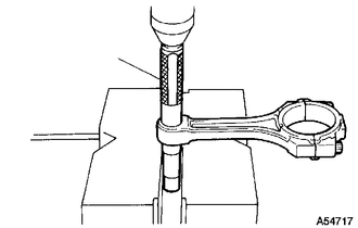
Using SST and a press, press out the bush.
- SST
- 09222-30010
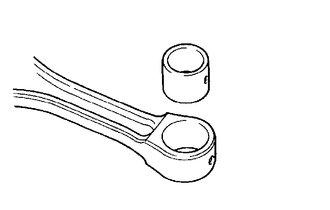
| *1 | Oil Hole |
Align the oil holes of a new bush and the connecting rod.
Using SST and a press, press in the bush.
- SST
- 09222-30010
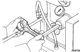
Using a pin hole grinder, hone the bush to obtain the standard specified clearance between the bush and piston pin.
Check that the piston pin fits at normal room temperature.
Coat the piston pin with engine oil and push it into the connecting rod with your thumb.
2.REPLACE TIGHT PLUG
- NOTICE:
-
If coolant leaks from a tight plug or a plug is corroded, replace it.
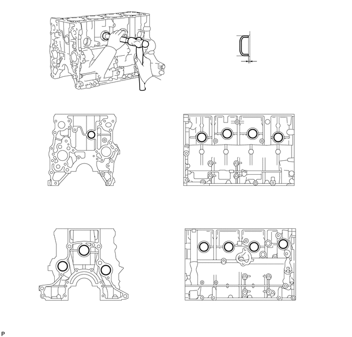
| *a | Front Side | *b | Intake Side |
| *c | Rear Side | *d | Exhaust Side |
Apply adhesive to new tight plugs.
- Adhesive:
Toyota Genuine Adhesive 1324, Three Bond 1324 or equivalent
Using SST, tap in the 8 tight plugs labeled A and C.
- SST
- 09950-60010 (09951-00350)
09950-70010 (09951-07100)
Using SST, tap in the tight plug labeled B.
- SST
- 09950-60010 (09951-00300)
09950-70010 (09951-07100)
Using SST, tap in the 3 tight plugs labeled D.
- SST
- 09950-60010 (09951-00400)
09950-70010 (09951-07100)
3.REPLACE STRAIGHT PIN
- NOTICE:
-
It is not necessary to remove a straight pin unless it is being replaced.
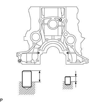
| *1 | Protrusion |
| *a | Rear Side |
Using a plastic-faced hammer, tap in new straight pins to the cylinder block.
- Standard Straight Pin:
Item Wide Protrusion Pin A 10 mm (0.394 in.) 13 mm (0.512 in.) Pin B 6.0 mm (0.236 in.) 5.5 mm (0.217 in.)
4.REPLACE RING PIN
- NOTICE:
-
It is not necessary to remove a ring pin unless it is being replaced.
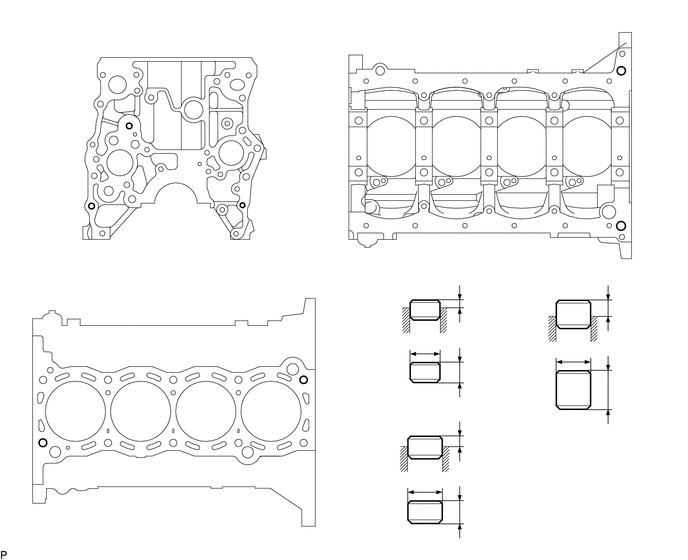 1.313,1.313 0.479,1.635 0.479,1.635 0.927,2.125 true 2.542,2.125 2.854,2.125 true 6.49,0.771 6.938,1.615 6.938,1.615 6.51,2.313 true 0.469,4.635 1.688,5.313 1.688,5.313 3.135,3.969 true 1.75,0.219 2,0.396 0.25,0.177 10 false *a 5.083,0.313 5.333,0.49 0.25,0.177 10 false *b 1.677,2.969 1.938,3.167 0.26,0.198 10 false *c 0.313,1.542 0.573,1.781 0.26,0.24 10 false A 4.375,4.063 4.5,4.229 0.125,0.167 10 false A 4.375,5.573 4.5,5.74 0.125,0.167 10 false B 5.927,4.365 6.063,4.521 0.135,0.156 10 false C 6.99,1.531 7.135,1.688 0.146,0.156 10 false C 1.646,5.354 1.771,5.51 0.125,0.156 10 false B 2.906,2.031 3.177,2.229 0.271,0.198 10 false A 4.865,3.781 5.042,3.958 0.177,0.177 10 false *1 6.417,3.969 6.594,4.146 0.177,0.177 10 false *1 4.854,5.25 5.031,5.427 0.177,0.177 10 false *1 4.365,4.938 4.542,5.115 0.177,0.177 10 false *2 4.354,3.51 4.531,3.688 0.177,0.177 10 false *2 5.875,3.594 6.052,3.771 0.177,0.177 10 false *2 4.865,4.5 5.042,4.677 0.177,0.177 10 false *3 4.865,3.073 5.042,3.25 0.177,0.177 10 false *3 6.417,3.104 6.594,3.281 0.177,0.177 10 false *3
*1 Height *2 Width *3 Protrusion - - *a Front Side *b Lower Side *c Upper Side - -
Using a plastic-faced hammer, tap in new ring pins to the cylinder block.
- Standard Ring Pin:
Item Height Width Protrusion Pin A 9.0 mm (0.354 in.) 11 mm (0.433 in.) 3.5 to 4.5 mm (0.138 to 0.177 in.) Pin B 14 mm (0.511 in.) 15 mm (0.591 in.) 7.5 to 9.5 mm (0.295 to 0.374 in.) Pin C 20 mm (0.787 in.) 14 mm (0.511 in.) 7.0 to 9.0 mm (0.276 to 0.354 in.)