RM1880E
_51
Engine / Hybrid System
_013216
2TR-FE STARTING
_0068501
IGNITION SWITCH
G
2TR-FE STARTING IGNITION SWITCH INSPECTION
PROCEDURE

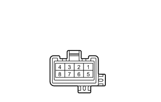
 1.INSPECT IGNITION SWITCH ASSEMBLY
a.
1.688,1.354 2.021,0.979
2.021,0.979 2.115,0.979
true
1.958,1.417 2.417,1.26
2.417,1.26 2.521,1.26
true
1.958,1.563 2.427,1.708
2.427,1.708 2.521,1.708
true
1.24,1.417 0.813,1.271
0.813,1.271 0.667,1.271
true
1.646,1.573 1.292,2.052
1.292,2.052 1.083,2.052
true
1.438,1.573 0.906,1.813
0.906,1.813 0.813,1.813
true
1.479,1.354 1.188,0.969
1.188,0.969 1.094,0.969
true
0.031,0 0.229,0.167
0.198,0.167
10
false
*a
2.156,0.896 2.5,1.052
0.344,0.156
10
false
ACC
2.563,1.188 2.813,1.344
0.25,0.156
10
false
IG1
0.833,1.969 1.104,2.125
0.271,0.156
10
false
IG2
2.573,1.625 2.896,1.781
0.323,0.156
10
false
AM2
0.344,1.188 0.667,1.344
0.323,0.156
10
false
AM1
0.521,1.729 0.823,1.875
0.302,0.146
10
false
ST2
0.813,0.896 1.115,1.042
0.302,0.146
10
false
ST1
| *a | Component without harness connected
(Ignition Switch) |
Measure the resistance according to the value(s) in the table below.
- Standard Resistance:
Tester Connection Switch Condition Specified Condition All combinations of all terminals LOCK 10 kΩ or higher 2 (ACC) - 4 (AM1) ACC Below 1 Ω 1 (IG1) - 4 (AM1)
2 (ACC) - 4 (AM1)
5 (AM2) - 6 (IG2)ON Below 1 Ω 1 (IG1) - 4 (AM1)
3 (ST1) - 4 (AM1)
5 (AM2) - 6 (IG2)
5 (AM2) - 7 (ST2)START Below 1 Ω
If the result is not as specified, replace the ignition switch assembly.