RM1880E
_58
Vehicle Interior
_013238
THEFT DETERRENT / KEYLESS ENTRY
_0068616
THEFT DETERRENT SYSTEM
J
THEFT DETERRENT / KEYLESS ENTRY THEFT DETERRENT SYSTEM Back Door Courtesy Switch Circuit
DESCRIPTION
The theft warning ECU assembly detects the condition of the back door lock assembly (back door courtesy light switch).
WIRING DIAGRAM
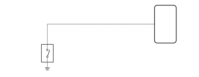
5.648,0.766 5.959,0.939
0.31,0.173
10
CTY
4.975,1.542 5.436,1.715
0.461,0.173
10
G124
4.975,1.722 6.856,1.895
1.881,0.173
10
Theft Warning ECU Assembly
1.978,1.65 2.197,1.823
0.219,0.173
10
V2
1.978,1.83 4.391,2.191
2.413,0.361
10
Back Door Lock Assembly (Back Door Courtesy Light Switch Assembly)
5.447,0.686 5.569,0.859
0.122,0.173
10
7
1.739,1.429 1.861,1.602
0.122,0.173
10
2
1.57,1.594 1.692,1.74
0.122,0.146
10
+
1.57,2.093 1.692,2.232
0.122,0.139
10
-
1.739,2.248 1.861,2.421
0.122,0.173
10
1
PROCEDURE
1.INSPECT BACK DOOR LOCK ASSEMBLY (BACK DOOR COURTESY SWITCH)
a.
Remove the back door lock assembly.
b.
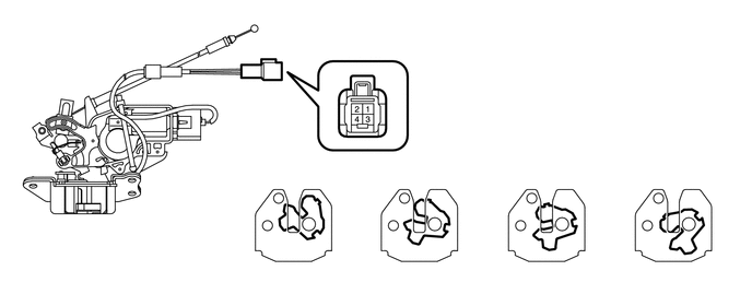
Measure the resistance according to the value(s) in the table below.
2.167,1.417 2.427,1.604
0.26,0.188
10
*a
2.219,2.083 2.521,2.333
0.302,0.25
10
*b
3.417,2.083 3.771,2.333
0.354,0.25
10
*c
4.635,2.083 4.927,2.333
0.292,0.25
10
*d
5.844,2.083 6.135,2.333
0.292,0.25
10
*e
| *a | Latch Condition | *b | Open-latch |
| *c | Half-latch | *d | Full-latch |
| *e | Over-latch | - | - |
- Standard Resistance:
Tester Connection Switch Condition Specified Condition 1 - 2 Open-latch (ON) Below 1 Ω Half-latch (ON) Below 1 Ω Full-latch (OFF) 10 kΩ or higher Over-latch (OFF) 10 kΩ or higher
- Result:
Proceed to OK NG
OK
2.CHECK HARNESS AND CONNECTOR (BACK DOOR LOCK - THEFT WARNING ECU AND BODY GROUND)
NG
2.CHECK HARNESS AND CONNECTOR (BACK DOOR LOCK - THEFT WARNING ECU AND BODY GROUND)
a.
Disconnect the V2 back door lock assembly (back door courtesy light switch) connector.
b.
Disconnect the G124 theft warning ECU assembly connector.
c.
Measure the resistance according to the value(s) in the table below.
- Standard Resistance:
Tester Connection Condition Specified Condition V2-2 (+) - G124-7 (CTY) Always Below 1 Ω V2-2 (+) or G124-7 (CTY) - Body ground Always 10 kΩ or higher V2-1 (-) - Body ground Always Below 1 Ω
- Result:
Proceed to OK NG
OK
PROCEED TO NEXT CIRCUIT INSPECTION SHOWN IN PROBLEM SYMPTOMS TABLE
Click hereVehicle Interior>THEFT DETERRENT / KEYLESS ENTRY>THEFT DETERRENT SYSTEM>PROBLEM SYMPTOMS TABLE
NG
REPAIR OR REPLACE HARNESS OR CONNECTOR