RM1880E
_58
Vehicle Interior
_013240
METER / GAUGE / DISPLAY
_0068630
METER / GAUGE SYSTEM
J
METER / GAUGE / DISPLAY METER / GAUGE SYSTEM Speedometer Malfunction
DESCRIPTION
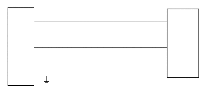
The combination meter receives vehicle speed signals from the speedometer sensor via the direct line.
WIRING DIAGRAM
5.708,2.844 7.01,3.396
1.302,0.552
10
false
Combination Meter Assembly
0.125,3.177 2.115,3.438
1.99,0.26
10
false
Speedometer Sensor
0.125,3 0.583,3.25
0.458,0.25
10
false
C38
5.708,2.677 6.219,2.938
0.51,0.26
10
false
G19
1.24,0.531 1.427,0.698
0.188,0.167
10
false
3
5.594,0.531 5.781,0.698
0.188,0.167
10
false
5
5.552,1.438 5.833,1.74
0.281,0.302
10
false
32
1.24,1.417 1.427,1.583
0.188,0.167
10
false
1
1.24,2.417 1.542,2.625
0.302,0.208
10
false
2
5.823,0.594 6.188,0.885
0.365,0.292
10
false
SI
5.833,1.531 6.458,1.969
0.625,0.438
10
false
MS5
0.958,0.625 1.281,0.885
0.323,0.26
10
false
SI
0.885,1.542 1.229,1.813
0.344,0.271
10
false
IG+
0.917,2.5 1.333,2.823
0.417,0.323
10
false
SE
PROCEDURE
1.CHECK SPEEDOMETER SENSOR (INPUT SIGNAL)
a.
Disconnect the G19 combination meter assembly connector.
b.
1.271,0.646 1.688,0.896
0.417,0.25
1.865,1.438 2.24,0.802
2.24,0.802 2.427,0.802
true
0.104,0.125 0.5,0.375
0.396,0.25
10
false
*a
1.344,0.688 1.74,0.938
0.396,0.25
10
false
G19
2.531,0.729 2.927,0.979
0.396,0.25
10
false
SI
2.938,3.625 3.333,3.875
0.396,0.25
10
false
GND
| *a | Component with harness connected
(Combination Meter Assembly) |
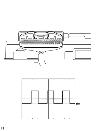
Using an oscilloscope, check the signal waveform of the meter.
- Measurement Condition:
Item Content Tester Connection G19-5 (SI) - Body ground Tool Setting 5 V/DIV., 20 msec./DIV. Condition Driving at approx. 20 km/h (12 mph)
- OK:
The waveform displayed is as shown in the illustration.
- HINT:
-
As the vehicle speed increases, the wavelength shortens.
- Result:
Proceed to OK NG
OK
REPLACE COMBINATION METER ASSEMBLY
NG
2.CHECK HARNESS AND CONNECTOR (SPEEDOMETER SENSOR - COMBINATION METER ASSEMBLY AND BODY GROUND)
2.CHECK HARNESS AND CONNECTOR (SPEEDOMETER SENSOR - COMBINATION METER ASSEMBLY AND BODY GROUND)
a.
Disconnect the C38 speedometer sensor connector.
b.
Disconnect the G19 combination meter assembly connector.
c.
Measure the resistance according to the value(s) in the table below.
- Standard Resistance:
Tester Connection Condition Specified Condition G19-5 (SI) - C38-3 (SI) Always Below 1 Ω G19-32 (MS5) - C38-1 (IG+) Always Below 1 Ω C38-1 (IG+) - C38-2 (SE) Always 10 kΩ or higher C38-1 (IG+) - C38-3 (SI) Always 10 kΩ or higher C38-2 (SE) - C38-3 (SI) Always 10 kΩ or higher C38-2 (SE) - Body ground Always Below 1 Ω
- Result:
Result Proceed to NG A OK (forA343E) B OK (for R150) C
A
REPAIR OR REPLACE HARNESS OR CONNECTOR
B
REPLACE SPEEDOMETER SENSOR
C
REPLACE SPEEDOMETER SENSOR