RM1880E
_58
Vehicle Interior
_013240
METER / GAUGE / DISPLAY
_0068630
METER / GAUGE SYSTEM
J
METER / GAUGE / DISPLAY METER / GAUGE SYSTEM Operating Light Control Rheostat does not Change Light Brightness
DESCRIPTION
When the light control rheostat knob is turned right, the combination meter and vehicle interior illumination will become brighter. When the light control rheostat knob is turned left, the combination meter and vehicle illumination will dim.
WIRING DIAGRAM
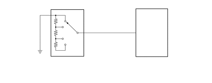
1.552,1.99 2.021,2.25
0.469,0.26
10
false
G31
1.563,2.146 3.167,2.5
1.604,0.354
10
false
Light Control Rheostat
4.313,1.969 4.927,2.292
0.615,0.323
10
false
G19
4.323,2.146 6.302,2.5
1.979,0.354
10
false
Combination Meter Assembly
4.427,0.927 4.708,1.219
0.281,0.292
10
false
9
2.917,0.917 3.115,1.146
0.198,0.229
10
false
1
1.573,0.333 1.865,0.594
0.292,0.26
10
false
2
4.677,1.031 5.052,1.344
0.375,0.313
10
false
ILL-
2.698,0.927 2.969,1.281
0.271,0.354
10
false
T
1.771,0.333 2.281,0.604
0.51,0.271
10
false
E
PROCEDURE
1.INSPECT LIGHT CONTROL RHEOSTAT
a.
Remove the light control rheostat.
Click hereVehicle Interior>METER / GAUGE / DISPLAY>LIGHT CONTROL RHEOSTAT>REMOVAL
b.
0.396,2.448 0.75,2.698
0.354,0.25
10
false
*f
1.625,0.063 1.927,0.323
0.302,0.26
10
false
*a
1.875,0.438 2.188,0.708
0.313,0.271
10
false
*e
2.365,0.76 2.719,1.021
0.354,0.26
10
false
*e
2.906,0.781 3.198,1.031
0.292,0.25
10
false
*c
2.323,0.24 2.646,0.521
0.323,0.281
10
false
*b
2.615,1.271 2.969,1.594
0.354,0.323
10
false
*e
3.115,1.521 3.344,1.865
0.229,0.344
10
false
*d
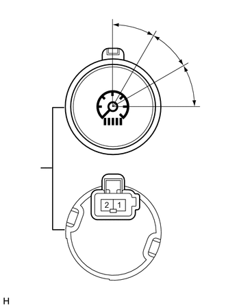
| *a | Position A |
| *b | Position B |
| *c | Position C |
| *d | Position D |
| *e | 30° |
| *f | Component without harness connected
(Light Control Rheostat) |
Measure the resistance according to the value(s) in the table below.
- Standard Resistance:
Tester Connection Switch Condition Specified Condition 1 - 2 Position A 666.9 to 737.1 Ω 1 - 2 Position B 220.4 to 243.6 Ω 1 - 2 Position C 77.9 to 86.1 Ω 1 - 2 Position D Below 1 Ω
- Result:
Proceed to OK NG
OK
2.CHECK HARNESS AND CONNECTOR (COMBINATION METER ASSEMBLY - LIGHT CONTROL RHEOSTAT)
NG
REPLACE LIGHT CONTROL RHEOSTAT
2.CHECK HARNESS AND CONNECTOR (COMBINATION METER ASSEMBLY - LIGHT CONTROL RHEOSTAT)
a.
Disconnect the G19 combination meter assembly connector.
b.
Disconnect the G31 light control rheostat connector.
c.
Measure the resistance according to the value(s) in the table below.
- Standard Resistance:
Tester Connection Condition Specified Condition G19-9 (ILL-) - G31-1 (T) Always Below 1 Ω G19-9 (ILL-) - Body ground Always 10 kΩ or higher G31-2 (E) - Body ground Always Below 1 Ω
- Result:
Proceed to OK NG
OK
REPLACE COMBINATION METER ASSEMBLY
NG
REPAIR OR REPLACE HARNESS OR CONNECTOR