RM1880E
_59
Vehicle Exterior
_013253
HORN
_0068748
INTEGRATION RELAY
G
HORN INTEGRATION RELAY ON-VEHICLE INSPECTION
PROCEDURE

 1.REMOVE UPPER RELAY BLOCK COVER
a.
Remove the upper relay block cover.
2.INSPECT NO. 1 INTEGRATION RELAY (HORN RELAY)
a.
0.542,1.76 1.313,1.917
1.313,1.917 1.51,1.917
true
1.74,1.917 1.896,1.917
1.896,1.917 2.75,1.792
true
1.563,1.823 1.823,2.094
0.26,0.271
10
false
*1
| *1 | Protective Tape |
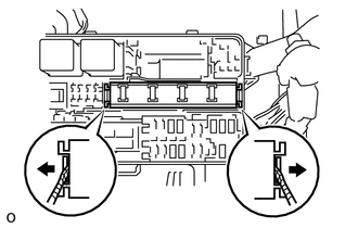
Using a screwdriver, detach the 2 claws and disconnect the No. 1 integration relay from the engine room junction block.
- HINT:
-
Tape the screwdriver tip before use.
b.
2.25,0.333 2.667,0.583
0.417,0.25
0.5,0.333 0.917,0.583
0.417,0.25
2.156,1.125 2.156,1.615
true
2.271,1.104 2.271,1.813
true
2.396,0.375 2.708,0.656
0.313,0.281
10
false
1I
0.604,0.375 0.885,0.677
0.281,0.302
10
false
1H
2.125,1.635 2.354,1.917
0.229,0.281
10
false
8
0.073,0.063 0.375,0.354
0.302,0.292
10
false
*a
2.24,1.833 2.479,2.063
0.24,0.229
10
false
7
| *a | Component with harness connected
(No. 1 Integration Relay) |
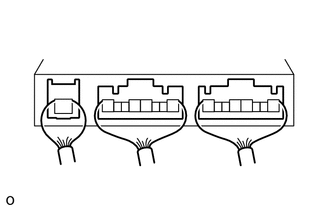
Measure the resistance according to the value(s) in the table below.
- Standard Resistance:
Tester Connection Condition Specified Condition 1I-8 - 1H-1 Battery voltage is not applied to terminals 1H-1 and 1I-7 10 kΩ or higher Battery voltage is applied to terminals 1H-1 and 1I-7 Below 1 Ω
If the result is not as specified, replace the No. 1 integration relay.
c.
Attach the 2 claws to install the No. 1 integration relay to the engine room junction block.
3.INSTALL UPPER RELAY BLOCK COVER
a.
Install the upper relay block cover.