Home › Engine / Hybrid System › 2TR-FE ENGINE MECHANICAL › CYLINDER HEAD › from 2014.08
RM1880E _51 Engine / Hybrid System _013210 2TR-FE ENGINE MECHANICAL _0068472 CYLINDER HEAD A

2TR-FE ENGINE MECHANICAL  CYLINDER HEAD  REASSEMBLY  


PROCEDURE

Hide 1.INSTALL STUD BOLT

NOTICE:

If a stud bolt is deformed or its threads are damaged, replace it.
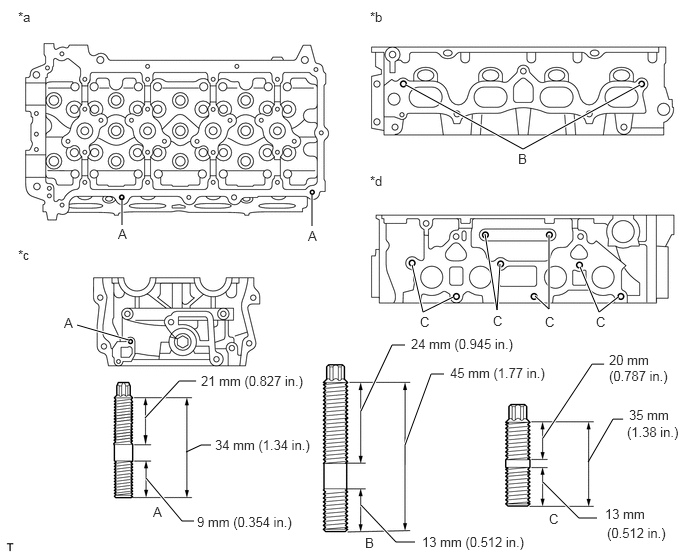

A170634C06
1.271,2.083 1.271,2.344 true 3.25,2.031 3.25,2.354 true 4.229,0.885 5.448,1.552 5.448,1.552 6.667,0.885 true 4.292,2.76 4.406,3.25 4.406,3.25 4.719,3.094 true 6.042,2.781 6.24,3.25 6.24,3.25 6.438,3.094 true 1.344,3.542 0.802,3.385 true 1.51,4.354 1.865,3.969 1.865,3.969 2.042,3.969 true 1.521,4.979 1.896,5.427 1.896,5.427 2.021,5.427 true 3.76,4.281 4.083,3.594 4.083,3.594 4.219,3.594 true 4.219,4.635 4.49,3.896 4.49,3.896 4.625,3.896 true 3.76,5.26 4.125,5.646 4.125,5.646 4.323,5.646 true 5.656,4.563 6.167,3.792 6.167,3.792 6.292,3.792 true 5.656,5.021 6.031,5.396 6.031,5.396 6.219,5.396 true 6.125,4.813 6.385,4.365 6.385,4.365 6.49,4.365 false 1.938,4.708 2.094,4.635 2.094,4.635 2.198,4.635 false 5.052,2.438 5.177,3.229 5.177,3.229 5.208,2.75 true 5.719,2.448 5.719,3.219 5.719,3.219 5.573,3.083 true 0.188,0.094 0.469,0.292 0.281,0.198 10 false *a 0.188,2.573 0.385,2.74 0.198,0.167 10 false *c 1.229,2.354 1.365,2.521 0.135,0.167 10 false A 0.667,3.281 0.792,3.438 0.125,0.156 10 false A 2.24,4.552 3.365,4.74 1.125,0.188 10 false 34 mm (1.34 in.) 2.052,5.354 3.188,5.521 1.135,0.167 10 false 9 mm (0.354 in.) 4.688,3.802 5.865,3.979 1.177,0.177 10 false 45 mm (1.77 in.) 1.594,5.25 1.729,5.417 0.135,0.167 10 false A 3.208,2.375 3.344,2.542 0.135,0.167 10 false A 4.375,3.271 4.51,3.438 0.135,0.167 10 false C 5.719,5.323 5.854,5.49 0.135,0.167 10 false C 5.135,3.26 5.271,3.427 0.135,0.167 10 false C 6.208,3.271 6.344,3.438 0.135,0.167 10 false C 5.396,1.573 5.531,1.74 0.135,0.167 10 false B 3.802,5.573 3.938,5.74 0.135,0.167 10 false B 3.854,0.094 4.052,0.26 0.198,0.167 10 false *b 3.854,1.802 4.052,1.969 0.198,0.167 10 false *d 2.094,3.885 3.365,4.104 1.271,0.219 10 false 21 mm (0.827 in.) 4.281,3.5 5.75,3.667 1.469,0.167 10 false 24 mm (0.945 in.) 4.396,5.563 5.729,5.75 1.333,0.188 10 false 13 mm (0.512 in.) 6.344,3.667 6.969,3.854 0.625,0.188 10 false 20 mm 6.302,5.271 6.948,5.5 0.646,0.229 10 false 13 mm 6.552,4.24 7.094,4.417 0.542,0.177 10 false 35 mm 6.344,3.833 7.156,4.052 0.813,0.219 10 false (0.787 in.) 6.531,4.417 7.156,4.604 0.625,0.188 10 false (1.38 in.) 5.677,3.271 5.813,3.438 0.135,0.167 10 false C 6.323,5.469 7.031,5.688 0.708,0.219 10 false (0.512 in.)
*a Cylinder Head Upper Side *b Intake Side
*c Front Side *d Exhaust Side


a.

Using E6, E7 and E8 "TORX" socket wrenches, install the stud bolts.

Torque:
for stud bolt A : 3.0 N*m (31 kgf*cm, 27 in.*lbf)
for stud bolt B and C : 7.5 N*m (76 kgf*cm, 66 in.*lbf)


Hide 2.INSTALL NO. 1 HEAD STRAIGHT SCREW PLUG

NOTICE:

If coolant leaks from a No. 1 head straight screw plug or a plug is corroded, replace it.


a.

Using a 10 mm hexagon wrench, install 3 new gaskets and the straight screw plugs.

Torque:
44 N*m (449 kgf*cm, 32 ft.*lbf)


Hide 3.INSTALL NO. 2 HEAD STRAIGHT SCREW PLUG

NOTICE:

If coolant leaks from the No. 2 head straight screw plug or the plug is corroded, replace it.


a.

Using a 19 mm hexagon wrench, install a new gasket and the straight screw plug.

Torque:
140 N*m (1428 kgf*cm, 103 ft.*lbf)


Hide 4.INSTALL VALVE SPRING SEAT

a.

Install the 16 valve spring seats to the cylinder head.


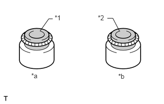
Hide 5.INSTALL VALVE STEM OIL SEAL

a.
A101414C02
0.844,0.646 1.021,0.396 1.021,0.396 1.104,0.396 false 2.5,0.646 2.365,0.385 2.365,0.385 2.25,0.385 false 2.052,0.292 2.208,0.479 0.156,0.188 10 false *2 1.146,0.292 1.313,0.49 0.167,0.198 10 false *1 0.656,1.51 0.865,1.708 0.208,0.198 10 false *a 2.479,1.521 2.677,1.719 0.198,0.198 10 false *b
*1 Gray
*2 Black
*a Intake Side
*b Exhaust Side


Apply a light coat of engine oil to new oil seals.

NOTICE:

Pay attention when installing the intake and exhaust oil seals. Installing an intake oil seal to the exhaust side or installing an exhaust oil seal to the intake side can cause installation problems later.


HINT:

The intake valve oil seals are gray and the exhaust valve oil seals are black.


b.
A101415C02
2.604,0.604 2.333,0.083 2.333,0.083 2.198,0.083 true 2.99,1.406 2.667,1.906 2.667,1.906 2.521,1.906 true 1.073,1.219 0.469,1.563 0.469,1.563 0.469,1.667 true 1.979,0 2.146,0.198 0.167,0.198 10 false *1 2.229,1.802 2.604,2 0.375,0.198 10 false SST 0.281,1.688 0.656,1.885 0.375,0.198 10 false SST
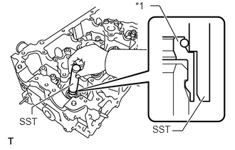
*1 Valve Stem Oil Seal


Using SST, push in the 16 oil seals to install them.

SST
09201-41020  

NOTICE:

Failure to use SST will cause the seal to be damaged or improperly seated.


Hide 6.INSTALL INTAKE VALVE

a.
A101416C09
2.652,1.492 2.849,1.687 0.197,0.195 10 *a
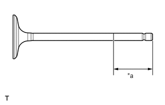
*a 30 mm (1.18 in.) or more


Apply plenty of engine oil to the tip area of the intake valve shown in the illustration.

b.
A333835

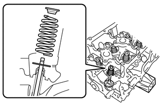
Install the valve, compression spring and spring retainer to the cylinder head.

NOTICE:

Install the same parts in the same combination to the original locations.


c.
A333831N01
1.583,0.333 1.708,0.333 1.708,0.333 1.823,0.708 true 1.25,0.24 1.573,0.427 0.323,0.188 10 false SST

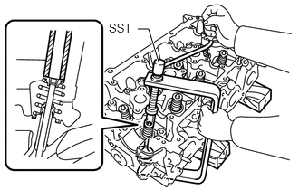
Using SST and wooden blocks, compress the spring and install the 2 retainer locks.

SST
09202-70020  
09202-00020  


d.
A333836C01
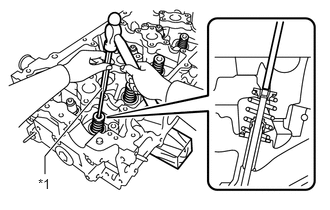
0.469,1.813 0.469,1.625 0.469,1.625 1.063,0.917 true 0.396,1.833 0.604,2.01 0.208,0.177 10 false *1
*1 5 mm Pin Punch


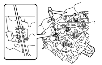
Using a 5 mm pin punch and plastic-faced hammer, lightly tap the valve stem tip to ensure a proper fit.

NOTICE:

Do not damage the valve stem tip.


Hide 7.INSTALL EXHAUST VALVE

a.
A101419C09
2.673,1.465 2.833,1.656 0.16,0.191 10 *a
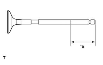
*a 30 mm (1.18 in.) or more


Apply plenty of engine oil to the tip area of the exhaust valve shown in the illustration.

b.
A333838

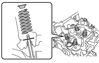
Install the valve, compression spring and spring retainer to the cylinder head.

NOTICE:

Install the same parts in the same combination to the original locations.


c.
A333832N01
0.635,0.417 0.771,0.208 0.771,0.208 0.979,0.208 false 1.031,0.115 1.354,0.302 0.323,0.188 10 false SST

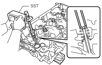
Using SST and wooden blocks, compress the spring and install the 2 retainer locks.

SST
09202-70020  
09202-00020  


d.
A333837C01
1.823,0.844 2.01,0.75 2.01,0.75 3.073,0.75 true 3.104,0.667 3.313,0.844 0.208,0.177 10 false *1
*1 5 mm Pin Punch


Using a 5 mm pin punch and plastic-faced hammer, lightly tap the valve stem tip to ensure a proper fit.

NOTICE:

Do not damage the valve stem tip.