- The center airbag sensor assembly receives a line short circuit signal, an open circuit signal, a short circuit to ground signal or a short circuit to B+ signal in the front airbag sensor RH circuit.
| Last Modified: 6-7-2017 | 6.8:8.0.40 | Doc ID: RM0000017Q9002X |
| Model Year Start: 2006 | Model: Land Cruiser | Prod Date Range: [05/2005 - ] |
| Title: SUPPLEMENTAL RESTRAINT SYSTEM: AIRBAG SYSTEM: B1100/31; Center Airbag Sensor Assembly Malfunction; 2006 MY Land Cruiser [05/2005 - ] | ||
|
DTC |
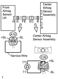
B1100/31 |
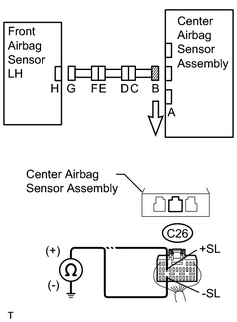
Center Airbag Sensor Assembly Malfunction |
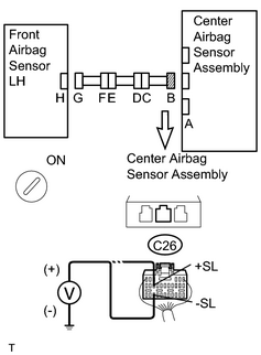
DESCRIPTION
The center airbag sensor assembly consists of the deceleration sensor, the safing sensor, the drive circuit, the diagnostic circuit, the ignition control, etc.
If the center airbag sensor assembly receives signals from the airbag sensor, it determines whether the airbags should be deployed and pretensioner squibs activated.
DTC B1100/31 is stored when a malfunction is detected in the center airbag sensor assembly, front airbag sensor RH circuit or front airbag sensor LH circuit.
|
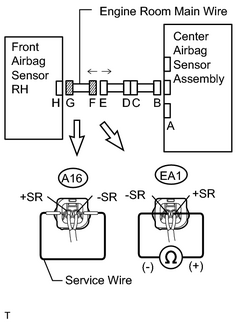
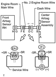
DTC No. |
DTC Detecting Condition |
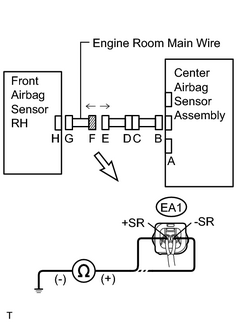
Trouble Area |
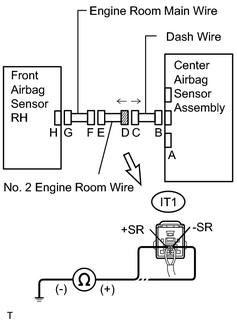
|---|---|---|
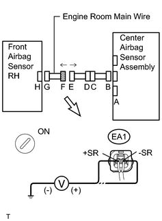
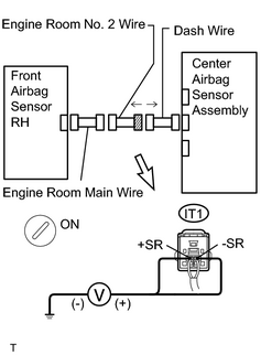
|
B1100/31 |
|
|
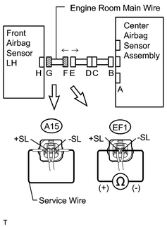
WIRING DIAGRAM
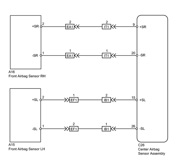
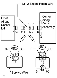
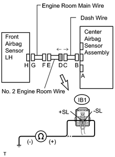
INSPECTION PROCEDURE
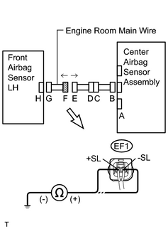
HINT:
When a trouble code is output simultaneously with B1100/31, repair the malfunction indicated by the other code (except B1100/31) first.
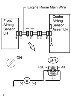
PROCEDURE
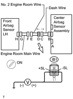
|
1. |
CHECK CONNECTORS |
(a) Turn the ignition switch off.
(b) Disconnect the cable from the negative (-) battery terminal, and wait for at least 90 seconds.
(c) Check that the connectors are properly connected to the center airbag sensor assembly, front airbag sensor RH and front airbag sensor LH. Also check that the connectors that link the engine room main wire, No. 2 engine room wire and dash wire are properly connected.
OK:
The connectors are properly connected.
HINT:
If the connectors are not connected securely, reconnect the connectors and proceed to the next inspection.
(d) Disconnect the connectors from the center airbag sensor assembly, front airbag sensor RH and front airbag sensor LH. Also disconnect the connectors that link the engine room main wire, No. 2 engine room wire and dash wire.
(e) Check that the terminals of connectors are not damaged.
OK:
The terminals are not deformed or damaged.
| NG |

|
|

|
2. |
CHECK FRONT AIRBAG SENSOR RH CIRCUIT (OPEN) |
|
(a) Connect the connectors that link the engine room main wire, No. 2 engine room wire and dash wire. |
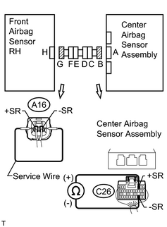
|
(b) Using a service wire, connect terminals A16-2 (+SR) and A16-1 (-SR) of connector G.
NOTICE:
Do not forcibly insert a service wire into the terminals of the connector when connecting.
(c) Measure the resistance according to the value(s) in the table below.
Standard Resistance:
|
Tester Connection |
Condition |
Specified Condition |
|---|---|---|
|
C26-9 (+SR) - C26-20 (-SR) |
Always |
Below 1 Ω |
| NG |
|
|
|
3. |
CHECK FRONT AIRBAG SENSOR RH CIRCUIT (SHORT) |
|
(a) Disconnect the service wire from connector G. |
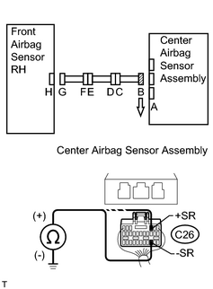
|
(b) Measure the resistance according to the value(s) in the table below.
Standard Resistance:
|
Tester Connection |
Condition |
Specified Condition |
|---|---|---|
|
C26-9 (+SR) - C26-20 (-SR) |
Always |
1 MΩ or higher |
| NG |
|
|
|
4. |
CHECK FRONT AIRBAG SENSOR RH CIRCUIT (SHORT TO B+) |
|
(a) Connect the negative (-) terminal cable to the battery, and wait for at least 2 seconds. |
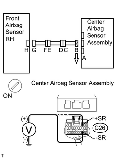
|
(b) Turn the ignition switch to ON.
(c) Measure the voltage according to the value(s) in the table below.
Standard Voltage:
|
Tester Connection |
Condition |
Specified Condition |
|---|---|---|
|
C26-9 (+SR) - Body ground |
Ignition switch ON |
Below 1 V |
|
C26-20 (-SR) - Body ground |
Ignition switch ON |
Below 1 V |
| NG |
|
|
|
5. |
CHECK FRONT AIRBAG SENSOR RH CIRCUIT (SHORT TO GROUND) |
|
(a) Turn the ignition switch off. |
|
(b) Disconnect the negative (-) terminal cable from the battery, and wait for at least 90 seconds.
(c) Measure the resistance according to the value(s) in the table below.
Standard Resistance:
|
Tester Connection |
Condition |
Specified Condition |
|---|---|---|
|
C26-9 (+SR) - Body ground |
Always |
1 MΩ or higher |
|
C26-20 (-SR) - Body ground |
Always |
1 MΩ or higher |
| NG |
|
|
|
6. |
CHECK FRONT AIRBAG SENSOR LH CIRCUIT (OPEN) |
|
(a) Connect the connectors that link the engine room main wire, No. 2 engine room wire and dash wire. |
|
(b) Using a service wire, connect terminals A15-2 (+SL) and A15-1 (-SL) of connector G.
NOTICE:
Do not forcibly insert a service wire into the terminals of the connector when connecting.
(c) Measure the resistance according to the value(s) in the table below.
Standard Resistance:
|
Tester Connection |
Condition |
Specified Condition |
|---|---|---|
|
C26-15 (+SL) - C26-26 (-SL) |
Always |
Below 1 Ω |
| NG |
|
|
|
7. |
CHECK FRONT AIRBAG SENSOR LH CIRCUIT (SHORT) |
|
(a) Disconnect the service wire from connector G. |
|
(b) Measure the resistance according to the value(s) in the table below.
Standard Resistance:
|
Tester Connection |
Condition |
Specified Condition |
|---|---|---|
|
C26-15 (+SL) - C26-26 (-SL) |
Always |
1 MΩ or higher |
| NG |
|
|
|
8. |
CHECK FRONT AIRBAG SENSOR LH CIRCUIT (SHORT TO B+) |
|
(a) Connect the negative (-) terminal cable to the battery, and wait for at least 2 seconds. |
|
(b) Turn the ignition switch to ON.
(c) Measure the voltage according to the value(s) in the table below.
Standard Voltage:
|
Tester Connection |
Condition |
Specified Condition |
|---|---|---|
|
C26-15 (+SL) - Body ground |
Ignition switch ON |
Below 1 V |
|
C26-26 (-SL) - Body ground |
Ignition switch ON |
Below 1 V |
| NG |
|
|
|
9. |
CHECK FRONT AIRBAG SENSOR LH CIRCUIT (SHORT TO GROUND) |
|
(a) Turn the ignition switch off. |
|
(b) Disconnect the negative (-) terminal cable from the battery, and wait for at least 90 seconds.
(c) Measure the resistance according to the value(s) in the table below.
Standard Resistance:
|
Tester Connection |
Condition |
Specified Condition |
|---|---|---|
|
C26-15 (+SL) - Body ground |
Always |
1 MΩ or higher |
|
C26-26 (-SL) - Body ground |
Always |
1 MΩ or higher |
| NG |
|
|
|
10. |
CHECK CENTER AIRBAG SENSOR ASSEMBLY |
(a) Connect the connector to the center airbag sensor assembly.
(b) Connect the negative (-) terminal cable to the battery, and wait for at least 2 seconds.
(c) Turn the ignition switch to ON, and wait for at least 60 seconds.
(d)
Clear the DTCs stored in memory
![2006 MY Land Cruiser [05/2005 - ]; SUPPLEMENTAL RESTRAINT SYSTEM: AIRBAG SYSTEM: DTC CHECK / CLEAR](../../../../stylegraphics/info.gif "2006 MY Land Cruiser [05/2005 - ]; SUPPLEMENTAL RESTRAINT SYSTEM: AIRBAG SYSTEM: DTC CHECK / CLEAR") .
.
(e) Turn the ignition switch off.
(f) Turn the ignition switch to ON, and wait for at least 60 seconds.
(g)
Check the DTCs
.
|
Result |
Proceed to |
|---|---|
|
DTC B1148/36 and B1149/37 are output, but B1100/31 is not output. |
A |
|
DTC B1100/31, B1148/36 and B1149/37 are output. |
B |
HINT:
Codes other than DTC B1100/31, B1148/36 and B1149/37 may be output at this time, but they are not related to this check.
| B |
|
|
|
11. |
CHECK FRONT AIRBAG SENSOR LH |
(a) Turn the ignition switch off.
(b) Disconnect the negative (-) terminal cable from the battery, and wait for at least 90 seconds.
(c) Connect the connector to the front airbag sensor LH.
(d) Connect the negative (-) terminal cable to the battery, and wait for at least 2 seconds.
(e) Turn the ignition switch to ON, and wait for at least 60 seconds.
(f)
Clear the DTCs stored in memory
.
(g) Turn the ignition switch off.
(h) Turn the ignition switch to ON, and wait for at least 60 seconds.
(i)
Check the DTCs
.
|
Result |
Proceed to |
|---|---|
|
DTC B1148/36 is output, but B1100/31 is not output. |
A |
|
DTC B1100/31 and B1148/36 are output. |
B |
HINT:
Codes other than DTC B1100/31 and B1148/36 may be output at this time, but they are not related to this check.
| B |
|
|
|
12. |
CHECK FRONT AIRBAG SENSOR RH |
(a) Turn the ignition switch off.
(b) Disconnect the negative (-) terminal cable from the battery, and wait for at least 90 seconds.
(c) Connect the connector to the front airbag sensor RH.
(d) Connect the negative (-) terminal cable to the battery, and wait for at least 2 seconds.
(e) Turn the ignition switch to ON, and wait for at least 60 seconds.
(f)
Clear the DTCs stored in memory
.
(g) Turn the ignition switch off.
(h) Turn the ignition switch to ON, and wait for at least 60 seconds.
(i)
Check the DTCs
.
|
Result |
Proceed to |
|---|---|
|
DTC B1100/31 is not output. |
A |
|
DTC B1100/31 is output. |
B |
HINT:
Codes other than DTC B1100/31 may be output at this time, but they are not related to this check.
| B |
|
| A |
|
|
13. |
CHECK ENGINE ROOM MAIN WIRE (OPEN) |
|
(a) Disconnect the engine room main wire connector from the No. 2 engine room wire. HINT: The service wire has already been inserted into connector G. |
|
(b) Measure the resistance according to the value(s) in the table below.
Standard Resistance:
|
Tester Connection |
Condition |
Specified Condition |
|---|---|---|
|
EA1-2 (+SR) - EA1-1 (-SR) |
Always |
Below 1 Ω |
| NG |
|
|
|
14. |
CHECK NO. 2 ENGINE ROOM WIRE (OPEN) |
|
(a) Disconnect the No. 2 engine room wire connector from the dash wire. |
|
(b) Using a service wire, connect terminals EA1-2 (+SR) and EA1-1 (-SR) of connector E.
NOTICE:
Do not forcibly insert a service wire into the terminals of the connector when connecting.
(c) Measure the resistance according to the value(s) in the table below.
Standard Resistance:
|
Tester Connection |
Condition |
Specified Condition |
|---|---|---|
|
IT1-2 (+SR) - IT1-1 (-SR) |
Always |
Below 1 Ω |
| NG |
|
| OK |
|
|
15. |
CHECK ENGINE ROOM MAIN WIRE (SHORT) |
|
(a) Disconnect the engine room main wire connector from the No. 2 engine room wire. |
|
(b) Measure the resistance according to the value(s) in the table below.
Standard Resistance:
|
Tester Connection |
Condition |
Specified Condition |
|---|---|---|
|
EA1-2 (+SR) - EA1-1 (-SR) |
Always |
1 MΩ or higher |
| NG |
|
|
|
16. |
CHECK NO. 2 ENGINE ROOM WIRE (SHORT) |
|
(a) Disconnect the No. 2 engine room wire connector from the dash wire. |
|
(b) Measure the resistance according to the value(s) in the table below.
Standard Resistance:
|
Tester Connection |
Condition |
Specified Condition |
|---|---|---|
|
IT1-2 (+SR) - IT1-1 (-SR) |
Always |
1 MΩ or higher |
| NG |
|
| OK |
|
|
17. |
CHECK ENGINE ROOM MAIN WIRE (SHORT TO B+) |
|
(a) Turn the ignition switch off. |
|
(b) Disconnect the negative (-) terminal cable from the battery, and wait for at least 90 seconds.
(c) Disconnect the engine room main wire connector from the No. 2 engine room wire.
(d) Connect the negative (-) terminal cable to the battery, and wait for at least 2 seconds.
(e) Turn the ignition switch to ON.
(f) Measure the voltage according to the value(s) in the table below.
Standard Voltage:
|
Tester Connection |
Condition |
Specified Condition |
|---|---|---|
|
EA1-2 (+SR) - Body ground |
Ignition switch ON |
Below 1 V |
|
EA1-1 (-SR) - Body ground |
Ignition switch ON |
Below 1 V |
| NG |
|
|
|
18. |
CHECK NO. 2 ENGINE ROOM WIRE (SHORT TO B+) |
|
(a) Turn the ignition switch off. |
|
(b) Disconnect the negative (-) terminal cable from the battery, and wait for at least 90 seconds.
(c) Disconnect the No. 2 engine room wire connector from the dash wire.
(d) Connect the negative (-) terminal cable to the battery, and wait for at least 2 seconds.
(e) Turn the ignition switch to ON.
(f) Measure the voltage according to the value(s) in the table below.
Standard Voltage:
|
Tester Connection |
Condition |
Specified Condition |
|---|---|---|
|
IT1-2 (+SR) - Body ground |
Ignition switch ON |
Below 1 V |
|
IT1-1 (-SR) - Body ground |
Ignition switch ON |
Below 1 V |
| NG |
|
| OK |
|
|
19. |
CHECK ENGINE ROOM MAIN WIRE (SHORT TO GROUND) |
|
(a) Disconnect the engine room main wire connector from the No. 2 engine room wire. |
|
(b) Measure the resistance according to the value(s) in the table below.
Standard Resistance:
|
Tester Connection |
Condition |
Specified Condition |
|---|---|---|
|
EA1-2 (+SR) - Body ground |
Always |
1 MΩ or higher |
|
EA1-1 (-SR) - Body ground |
Always |
1 MΩ or higher |
| NG |
|
|
|
20. |
CHECK NO. 2 ENGINE ROOM WIRE (SHORT TO GROUND) |
|
(a) Disconnect the No. 2 engine room wire connector from the dash wire. |
|
(b) Measure the resistance according to the value(s) in the table below.
Standard Resistance:
|
Tester Connection |
Condition |
Specified Condition |
|---|---|---|
|
IT1-2 (+SR) - Body ground |
Always |
1 MΩ or higher |
|
IT1-1 (-SR) - Body ground |
Always |
1 MΩ or higher |
| NG |
|
| OK |
|
|
21. |
CHECK ENGINE ROOM MAIN WIRE (OPEN) |
|
(a) Disconnect the engine room main wire connector from the No. 2 engine room wire. HINT: The service wire has already been inserted into connector G. |
|
(b) Measure the resistance according to the value(s) in the table below.
Standard Resistance:
|
Tester Connection |
Condition |
Specified Condition |
|---|---|---|
|
EF1-1 (+SL) - EF1-2 (-SL) |
Always |
Below 1 Ω |
| NG |
|
|
|
22. |
CHECK NO. 2 ENGINE ROOM WIRE (OPEN) |
|
(a) Disconnect the No. 2 engine room wire connector from the dash wire. |
|
(b) Using a service wire, connect terminals EF1-1 (+SL) and EF1-2 (-SL) of connector E.
NOTICE:
Do not forcibly insert a service wire into the terminals of the connector when connecting.
(c) Measure the resistance according to the value(s) in the table below.
Standard Resistance:
|
Tester Connection |
Condition |
Specified Condition |
|---|---|---|
|
IB1-2 (+SL) - IB1-1 (-SL) |
Always |
Below 1 Ω |
| NG |
|
| OK |
|
|
23. |
CHECK ENGINE ROOM MAIN WIRE (SHORT) |
|
(a) Disconnect the engine room main wire connector from the No. 2 engine room wire. |
|
(b) Measure the resistance according to the value(s) in the table below.
Standard Resistance:
|
Tester Connection |
Condition |
Specified Condition |
|---|---|---|
|
EF1-1 (+SL) - EF1-2 (-SL) |
Always |
1 MΩ or higher |
| NG |
|
|
|
24. |
CHECK NO. 2 ENGINE ROOM WIRE (SHORT) |
|
(a) Disconnect the No. 2 engine room wire connector from the dash wire. |
|
(b) Measure the resistance according to the value(s) in the table below.
Standard Resistance:
|
Tester Connection |
Condition |
Specified Condition |
|---|---|---|
|
IB1-2 (+SL) - IB1-1 (-SL) |
Always |
1 MΩ or higher |
| NG |
|
| OK |
|
|
25. |
CHECK ENGINE ROOM MAIN WIRE (SHORT TO B+) |
|
(a) Turn the ignition switch off. |
|
(b) Disconnect the negative (-) terminal cable from the battery, and wait for at least 90 seconds.
(c) Disconnect the engine room main wire connector from the No. 2 engine room wire.
(d) Connect the negative (-) terminal cable to the battery, and wait for at least 2 seconds.
(e) Turn the ignition switch to ON.
(f) Measure the voltage according to the value(s) in the table below.
Standard Voltage:
|
Tester Connection |
Condition |
Specified Condition |
|---|---|---|
|
EF1-1 (+SL) - Body ground |
Ignition switch ON |
Below 1 V |
|
EF1-2 (-SL) - Body ground |
Ignition switch ON |
Below 1 V |
| NG |
|
|
|
26. |
CHECK NO. 2 ENGINE ROOM WIRE (SHORT TO B+) |
|
(a) Turn the ignition switch off. |
|
(b) Disconnect the negative (-) terminal cable from the battery, and wait for at least 90 seconds.
(c) Disconnect the No. 2 engine room wire connector from the dash wire.
(d) Connect the negative (-) terminal cable to the battery, and wait for at least 2 seconds.
(e) Turn the ignition switch to ON.
(f) Measure the voltage according to the value(s) in the table below.
Standard Voltage:
|
Tester Connection |
Condition |
Specified Condition |
|---|---|---|
|
IB1-2 (+SL) - Body ground |
Ignition switch ON |
Below 1 V |
|
IB1-1 (-SL) - Body ground |
Ignition switch ON |
Below 1 V |
| NG |
|
| OK |
|
|
27. |
CHECK ENGINE ROOM MAIN WIRE (SHORT TO GROUND) |
|
(a) Disconnect the engine room main wire connector from the No. 2 engine room wire. |
|
(b) Measure the resistance according to the value(s) in the table below.
Standard Resistance:
|
Tester Connection |
Condition |
Specified Condition |
|---|---|---|
|
EF1-1 (+SL) - Body ground |
Always |
1 MΩ or higher |
|
EF1-2 (-SL) - Body ground |
Always |
1 MΩ or higher |
| NG |
|
|
|
28. |
CHECK NO. 2 ENGINE ROOM WIRE (SHORT TO GROUND) |
|
(a) Disconnect the No. 2 engine room wire connector from the dash wire. |
|
(b) Measure the resistance according to the value(s) in the table below.
Standard Resistance:
|
Tester Connection |
Condition |
Specified Condition |
|---|---|---|
|
IB1-2 (+SL) - Body ground |
Always |
1 MΩ or higher |
|
IB1-1 (-SL) - Body ground |
Always |
1 MΩ or higher |
| NG |
|
| OK |
|

|

|