| Last Modified: 6-7-2017 | 6.8:8.0.40 | Doc ID: RM0000017QA002X |
| Model Year Start: 2006 | Model: Land Cruiser | Prod Date Range: [05/2005 - ] |
| Title: SUPPLEMENTAL RESTRAINT SYSTEM: AIRBAG SYSTEM: Source Voltage Drop; 2006 MY Land Cruiser [05/2005 - ] | ||
|
Source Voltage Drop |
DESCRIPTION
The SRS is equipped with a voltage-increase circuit (DC-DC converter) in the center airbag sensor in case the source voltage drops.
When the battery voltage drops, the voltage-increase circuit (DC-DC converter) functions to increase the voltage of the SRS to normal voltage.
The diagnosis system malfunction display for this circuit is different from the other circuits in that when the SRS warning light remains on and the DTC shows a normal code, source voltage drop is indicated.
Malfunction in this circuit is not recorded in the center airbag sensor, and when the source voltage returns to normal, the SRS warning light automatically goes off.
|
DTC No. |
Diagnosis |
|---|---|
|
(Normal) |
Source voltage drop |
WIRING DIAGRAM
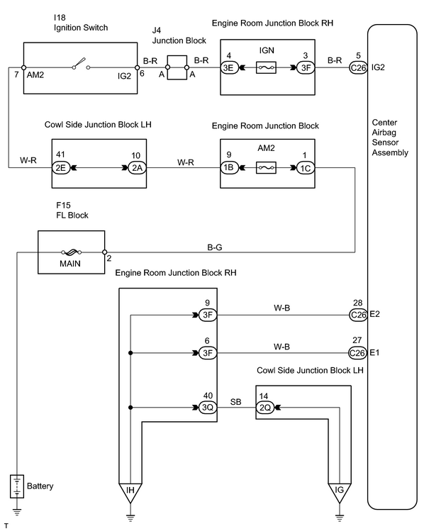
INSPECTION PROCEDURE
PROCEDURE
|
1. |
CHECK SOURCE VOLTAGE |
|
(a) Turn the ignition switch to LOCK. (b) Disconnect the negative (-) terminal cable from the battery, and wait for at least 90 seconds. (c) Disconnect the connectors of the center airbag sensor. (d) Disconnect the steering wheel pad connector. (e) Disconnect the front passenger airbag connector. (f) Disconnect the side airbag connectors. (g) Disconnect the seat belt pretensioner connectors. (h) Disconnect the center airbag sensor connectors. (i) Disconnect the front airbag sensor connectors. (j) Disconnect the side and curtain shield center airbag sensor connectors. (k) Disconnect the curtain shield airbag connectors. (l) Disconnect the curtain shield center airbag sensor connectors. (m) Disconnect the seat position sensor connector. (n) Disconnect the front seat inner belt LH connector. (o) Disconnect the negative (-) terminal cable to the battery. (p) Turn the ignition switch to ON. (q) Measure the voltage between the body ground and terminal IG2 of the C26 connector on the center airbag sensor and operate electric system (defogger, wiper, headlight, heater blower, etc.). Standard resistance: 10 to 14 V |
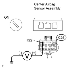
|
| NG |

|
CHECK HARNESS BETWEEN BATTERY AND AIRBAG SENSOR ASSEMBLY, AND CHECK BATTERY AND CHARGING SYSTEM |
|

|
2. |
CHECK WIRE HARNESS (CENTER AIRBAG SENSOR ASSEMBLY - BODY GROUND) |
|
(a) Measure the resistance between the body ground and each of terminals E1 and E2 of the C26 center airbag sensor connector. Standard resistance: Below 1Ω |
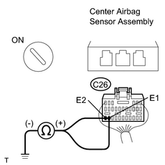
|
| NG |
|
|
|
3. |
CHECK SRS WARNING LIGHT |
|
(a) Turn the ignition switch to LOCK. (b) Disconnect the negative (-) terminal cable from the battery, and wait for at least 90 seconds. (c) Connect the steering wheel pad connector. (d) Connect the front passenger airbag connector. (e) Connect the side airbag connectors. (f) Connect the seat belt pretensioner connectors. (g) Connect the center airbag sensor connectors. (h) Connect the front airbag sensor connectors. (i) Connect the side and curtain shield center airbag sensor connectors. (j) Connect the curtain shield airbag connectors. (k) Connect the curtain shield center airbag sensor connectors. (l) Connect the seat position sensor connector. (m) Connect the front seat inner belt LH connector. (n) Turn the ignition switch to ON. (o) Operate electric system (defogger, wiper, headlight, heater blower, etc.) and check that SRS warning light goes off. |
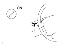
|
| NG |
|
| OK |
|

|

|