- Tire pressure monitor valve sub-assembly
- Tire pressure monitor ECU
- Tire pressure warning select switch
- Tire pressure warning reset switch
- Wire harness
| Last Modified: 6-7-2017 | 6.8:8.0.40 | Doc ID: RM0000018LI000X |
| Model Year Start: 2006 | Model: Land Cruiser | Prod Date Range: [05/2005 - ] |
| Title: TIRE AND WHEEL: TIRE PRESSURE WARNING SYSTEM: C2177/77; Initialization not Completed; 2006 MY Land Cruiser [05/2005 - ] | ||
|
DTC |
C2177/77 |
Initialization not Completed |
DESCRIPTION
Initialization is necessary after replacing the ECU, tires with tires of different pressures or a tire pressure monitor valve sub-assembly, after rotating the tires or when a new vehicle is delivered.
|
DTC No. |
DTC Detection Condition |
Trouble Area |
|---|---|---|
|
C2177/77 |
Initialization is not complete after vehicle speed of 5 mph (8 km/h) or more continues for 20 minutes or more (total). |
|
WIRING DIAGRAM
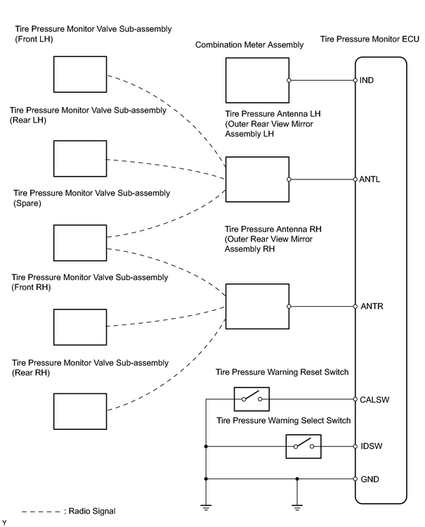
INSPECTION PROCEDURE
NOTICE:
It is necessary to register an ID code after replacing the tire pressure monitor valve sub-assembly and/or the tire pressure monitor ECU
![2006 MY Land Cruiser [05/2005 - ]; TIRE AND WHEEL: TIRE PRESSURE WARNING SYSTEM: REGISTRATION](../../../../stylegraphics/info.gif "2006 MY Land Cruiser [05/2005 - ]; TIRE AND WHEEL: TIRE PRESSURE WARNING SYSTEM: REGISTRATION") .
.
HINT:
Set the tire pressure to the specified value.
PROCEDURE
|
1. |
CHECK TIRE PRESSURE WARNING LIGHT |
(a) Check the tire pressure warning light.
Result
|
Condition |
Proceed to |
|---|---|
|
Does not blink |
A |
|
Comes on and goes off repeatedly at 0.5 second intervals |
B |
| B |

|
|

|
2. |
CLEAR DTC |
(a)
Clear the DTC
.
|
|
3. |
CHECK DTC |
(a)
Check for DTC
.
OK:
DTC C2177/77 is not output.
| OK |
|
|
|
4. |
CHECK TIRE PRESSURE WARNING LIGHT |
(a) Turn the ignition switch ON.
(b) Check that the tire pressure warning light comes on for 3 seconds and goes off.
Result
|
Condition |
Proceed to |
|---|---|
|
Does not come on |
A |
|
Comes on |
B |
| B |
|
|
|
5. |
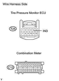
CHECK WIRE HARNESS (ECU - COMBINATION METER) |
|
(a) Disconnect the T25 ECU connector. |
|
(b) Disconnect the C13 combination meter connector.
(c) Measure the resistance of the wire harness side connectors.
Standard resistance:
|
Tester Connection |
Specified Condition |
|---|---|
|
T25-5 (IND) - C13-13 |
Below 1 Ω |
|
T25-5 (IND) - Body ground |
10 kΩ or higher |
| NG |
|
|
|
6. |
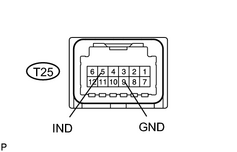
INSPECT TIRE PRESSURE MONITOR ECU |
|
(a) Connect the T25 ECU connector. |
|
(b) Measure the voltage wire harness connector.
Standard voltage:
|
Tester Connection |
Condition |
Specified Condition |
|---|---|---|
|
T25-5 (IND) - T25-9 (GND) |
Immediately after turning the ignition switch ON (within 3 seconds) |
8 to 16 V |
| NG |
|
| OK |
|
|
7. |
CHECK TIRE PRESSURE WARNING LIGHT |
(a)
Enter TEST MODE
.
(b) Press the tire pressure warning reset switch for 1 second or more after switching to TEST MODE.
(c) Check that the tire pressure warning light comes on while pressing the tire pressure warning reset switch.
Result
|
Condition |
Proceed to |
|---|---|
|
Comes on |
A |
|
Does not come on |
B |
| B |
|
|
|
8. |
CHECK TIRE PRESSURE WARNING LIGHT |
(a) Turn the ignition switch ON.
(b) Rapidly reduce the pressure of the tires to approximately 120 kPa (1.2 kgf/cm 2 , 35 psi).
(c) Check that the tire pressure warning light comes on for 1 second while rapidly reducing the pressure or immediately after reducing the pressure.
(d) Note the check results.
(e) Set the tire pressure to the specified value.
(f) Check that the tire pressure warning light comes on when each of the wheels is inspected.
Result
|
Result |
Proceed to |
|---|---|
|
Does not come on (All wheels) |
A |
|
Does not come on (Some wheels) |
B |
|
Comes on (All wheels) |
C |
HINT:
Replace the tire pressure monitor valve sub-assembly for which the tire pressure warning light did not come on during inspection.
| B |
|
| C |
|
|
|
9. |
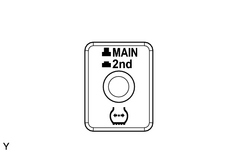
CHECK TIRE PRESSURE SELECT SWITCH POSITION |
|
(a) Check that the position of the select switch (MAIN or 2nd) is the same as the type of registration ID of the wheels being used. |
|
| NG |
|
|
|
10. |
CHECK TEST MODE DTC |
(a)
Check for test mode DTC
.
Result
|
Result |
Proceed to |
|---|---|
|
C2195/95 output |
A |
|
C2195/95 not output |
B |
| B |
|
|
|
11. |
CHECK WIRE HARNESS (ANTENNA - ECU) |
|
(a) Disconnect the T26 ECU connector. |
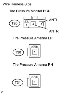
|
(b) Disconnect the T30 and T31 antenna connectors.
(c) Measure the resistance of the wire harness side connectors.
Standard resistance:
|
Tester Connection |
Specified Condition |
|---|---|
|
T26-3 (ANTL) - T30-1 |
Below 1 Ω |
|
T26-2 (ANTR) - T31-1 |
Below 1 Ω |
| NG |
|
|
|
12. |
REPLACE OUTER REAR VIEW MIRROR ASSEMBLY (TIRE PRESSURE ANTENNA) |
|
|
13. |
CHECK DTC |
(a)
Check for DTC
.
OK:
DTC is not output.
| OK |
|
| NG |
|
|
14. |
CHECK TIRE PRESSURE MONITOR ECU |
|
(a) Disconnect the T25 ECU connector. |
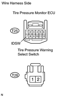
|
(b) Disconnect the T28 switch connector.
(c) Measure the resistance of the wire harness side connector.
Standard resistance:
|
Tester Connection |
Specified Condition |
|---|---|
|
T25-7 (IDSW) - T28-2 |
Below 1 Ω |
|
T25-7 (IDSW) - Body ground |
10 k Ω or higher |
|
T28-1 - Body ground |
Below 1 Ω |
| NG |
|
|
|
15. |
INSPECT TIRE PRESSURE WARNING SELECT SWITCH |
|
(a) Remove the select switch. |
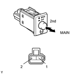
|
(b) Measure the resistance of the switch.
Standard resistance:
|
Tester Connection |
Switch Position |
Specified Condition |
|---|---|---|
|
1 - 2 |
MAIN |
10 k Ω or higher |
|
1 - 2 |
2nd |
Below 1 Ω |
| NG |
|
|
|
16. |
REPLACE TIRE PRESSURE MONITOR ECU |
|
|
17. |
CHECK DTC |
(a) Check for DTC.
OK:
DTC is not output
| OK |
|
| NG |
|
|
18. |
CHECK WIRE HARNESS (RESET SWITCH - ECU) |
|
(a) Disconnect the T27 switch connector. |
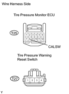
|
(b) Disconnect the T25 ECU connector.
(c) Measure the resistance of the wire harness side connectors.
Standard resistance:
|
Tester Connection |
Specified Condition |
|---|---|
|
T25-8 (CALSW) - T27-3 |
Below 1 Ω |
|
T25-8 (CALSW) - Body ground |
10 kΩ or higher |
| NG |
|
|
|
19. |
INSPECT TIRE PRESSURE MONITOR ECU |
|
(a) Connect the T25 ECU connector. |
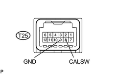
|
(b) Connect the T27 switch connector.
(c) Measure the voltage of the ECU.
Result
|
Tester Connection |
Connection |
Specified Condition |
|---|---|---|
|
Z34-8 (CALSW) - Z34-9 (GND) |
Ignition switch ON Reset switch ON |
Below 1.5 V |
|
Z34-8 (CALSW) - Z34-9 (GND) |
Ignition switch ON Reset switch OFF |
8 to 15 V |
| NG |
|
| OK |
|

|

|