| Last Modified: 6-7-2017 | 6.8:8.0.40 | Doc ID: RM000001909002X |
| Model Year Start: 2006 | Model: Land Cruiser | Prod Date Range: [05/2005 - ] |
| Title: MIRROR: POWER MIRROR CONTROL SYSTEM: INSPECTION; 2006 MY Land Cruiser [05/2005 - ] | ||
INSPECTION
1. INSPECT OUTER REAR VIEW MIRROR SWITCH ASSEMBLY
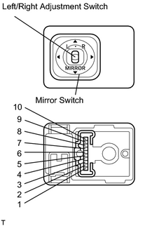
(a) The L side of the left/right adjustment switch:
Check the continuity of the mirror switch.
OK:
|
Tester Connection |
Switch Condition |
Specified Condition |
|---|---|---|
|
3 - 4 7 - 8 |
UP |
Continuity |
|
OFF |
No Continuity |
|
|
3 - 8 4 - 7 |
DOWN |
Continuity |
|
OFF |
No Continuity |
|
|
4 - 9 7 - 8 |
LEFT |
Continuity |
|
OFF |
No Continuity |
|
|
4 - 7 8 - 9 |
RIGHT |
Continuity |
|
OFF |
No Continuity |
If the continuity is not as specified, replace the switch.
(b) The R side of the left/right adjustment switch:
Check the continuity of the mirror switch.
OK:
|
Tester Connection |
Switch Condition |
Specified Condition |
|---|---|---|
|
2 - 4 7 - 8 |
UP |
Continuity |
|
OFF |
No Continuity |
|
|
4 - 7 2 - 8 |
DOWN |
Continuity |
|
OFF |
No Continuity |
|
|
4 - 10 7 - 8 |
LEFT |
Continuity |
|
OFF |
No Continuity |
|
|
4 - 7 8 - 10 |
RIGHT |
Continuity |
|
OFF |
No Continuity |
If the continuity is not as specified, replace the switch.
|
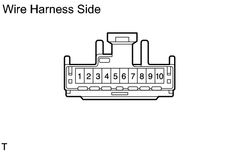
(c) Check the mirror switch circuit. (1) Disconnect the connector from the switch and check the connector on the wire harness side. OK:
If the circuit is not as specified, inspect the parts connected to the circuit. |
|
|
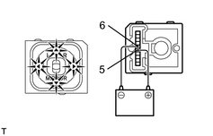
(d) Check the indicator light operation. (1) Connect the positive (+) lead from the battery to terminal 5 and the negative (-) lead to terminal 6, and check that the indicator light lights up. If the indicator light does not light up, replace the switch. |
|
2. INSPECT OUTER REAR VIEW MIRROR ASSEMBLY
(a) Check the mirror motor operation.
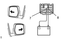
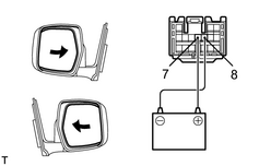
(1) Connect the positive (+) lead from the battery to terminal 8 and the negative (-) lead to terminal 7, and check that the mirror surface turns outward.
|
(2) Reverse the polarity of the battery leads, and check that the mirror surface turns inward. |
|
|
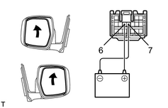
(3) Connect the battery positive (+) lead to terminal 6 and the battery negative (-) lead to terminal 7, and check that the mirror turns upward. |
|
|
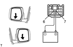
(4) Reverse the polarity of the battery leads, and check that the mirror turns downward. If the operation is not as specified, replace the mirror assembly. |
|

|

|