| Last Modified: 6-7-2017 | 6.8:8.0.40 | Doc ID: RM00000195V001X |
| Model Year Start: 2006 | Model: Land Cruiser | Prod Date Range: [05/2005 - ] |
| Title: WINDSHIELD / WINDOWGLASS: WINDSHIELD GLASS: INSTALLATION; 2006 MY Land Cruiser [05/2005 - ] | ||
INSTALLATION
HINT:
- Use the same procedures for the LH side and RH side.
-
A bolt without a torque specification is shown in the standard bolt chart
![2006 MY Land Cruiser [05/2005 - ]; SERVICE SPECIFICATIONS: STANDARD BOLT: SPECIFIED TORQUE FOR STANDARD BOLTS](../../../../stylegraphics/info.gif "2006 MY Land Cruiser [05/2005 - ]; SERVICE SPECIFICATIONS: STANDARD BOLT: SPECIFIED TORQUE FOR STANDARD BOLTS") .
.
1. INSTALL WINDSHIELD GLASS STOPPER
|
(a) Install 2 new stoppers onto the glass as shown in the illustration. Standard measurement:
|
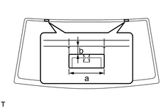
|
|
2. INSTALL WINDSHIELD GLASS ADHESIVE DAM (a) Install new dams with adhesive tape as shown in the illustration. Standard measurement:
NOTICE: Do not touch the glass surface after cleaning it. |
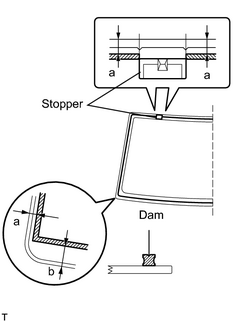
|
3. INSTALL WINDSHIELD GLASS
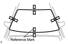
(a) Position the glass.
(1) Using suction cups, place the glass in the correct position.
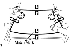
(2) Place matchmarks on the glass and vehicle body on the locations indicated in the illustration.
HINT:
- Placing matchmarks is only necessary when installing a new glass. If it is the reused glass, matchmarks should already be present.
- When reusing the glass, check and correct the matchmark positions.
NOTICE:
Check that the stoppers are attached to the vehicle body correctly.
(3) Using suction cups, remove the glass.
|
(b) Using a brush, apply Primer M to the exposed part of the vehicle body. NOTICE:
|
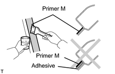
|
|
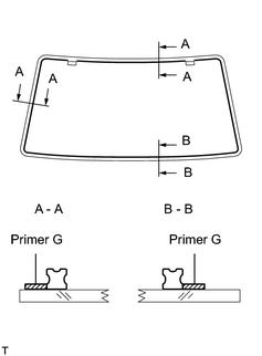
(c) Using a brush or sponge, apply Primer G to the contact surface of the glass. HINT: If the primer is applied to an area that is not specified, apply white gasoline to a clean cloth and wipe off the excess primer. NOTICE:
|
|
|
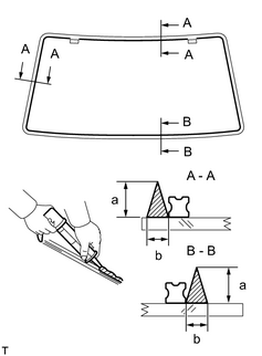
(d) Apply adhesive to the glass. Adhesive: Toyota Genuine Windshield, Glass Adhesive or Equivalent (1) Cut off the tip of the cartridge nozzle as shown in the illustration. HINT: After cutting off the tip, use all adhesive within the time written in the table below. Usage time frame:
(2) Load the sealer gun with the cartridge. (3) Apply adhesive to the glass as shown in the illustration. Standard measurement:
|
|
(e) Install the glass to the vehicle body.
(1) Using suction cups, position the glass so that the matchmarks are aligned. Press it in gently along the rim.
(2) Lightly press the outer surface of the glass to ensure that it is securely fit to the vehicle body.
NOTICE:
- Check that the stoppers are attached to the vehicle body correctly.
- Check that the vehicle body and glass have a small gap between them.
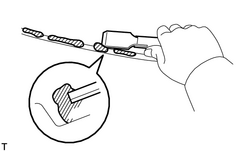
(3) Use a scraper to remove any excess or protruding adhesive.
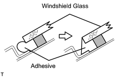
HINT:
Make sure that the dam is attached to the body panel, as shown in the illustration.
(4) Hold the glass in place securely with protective tape or equivalent until the adhesive hardens.
NOTICE:
Do not drive the vehicle for the amount of time written in the table below.
Minimum time:
|
Temperature |
Minimum time prior to driving vehicle |
|---|---|
|
35°C (95°F) |
1 hour 30 minutes |
|
20°C (68°F) |
5 hours |
|
5°C (41°F) |
24 hours |
4. CHECK FOR LEAKS AND REPAIR
(a) Conduct a leak test after the adhesive has completely hardened.
(b) Seal any leaks with auto glass sealer.
|
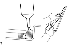
5. APPLY ADHESIVE TO MOULDING INSTALLATION AREA (a) Apply adhesive to the moulding installation area between the glass and the body. |
|
|
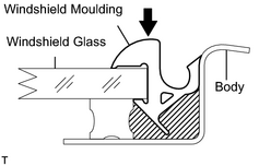
6. INSTALL WINDSHIELD MOULDING OUTER UPPER (a) Place a new moulding onto the body and tap it by hand. |
|
7. INSTALL NO. 2 WINDSHIELD MOULDING OUTSIDE
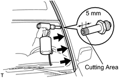
(a) Using an air riveter with No. 4 nose piece, install 4 new rivets and the moulding.
HINT:
Before using the air riveter with No. 4 nose piece, cut 5 mm (0.20 in.) at the edge of No. 4 nose piece.
CAUTION:
-
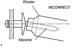 Do not prize a riveter. It could damage the riveter and cause loose fitting and mandrel bend.
-
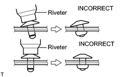 Do not tilt the riveter when fastening the rivet to the material to avoid loose fitting.
- Do not allow gap spacing between the rivet head and the material.
-
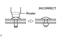 Do not allow gap spacing between the materials.
8. INSTALL COWL TOP VENTILATOR LOUVER LH
9. INSTALL COWL TOP VENTILATOR LOUVER RH
10. INSTALL HOOD TO COWL TOP SEAL
11. INSTALL FRONT WIPER ARM
12. INSTALL FRONT WIPER ARM HEAD CAP
|
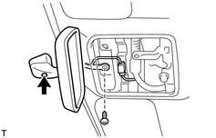
13. INSTALL INNER REAR VIEW MIRROR ASSEMBLY (a) Install the mirror with the 2 screws. (b) Connect the connector. |
|
14. INSTALL ROOF HEADLINING ASSEMBLY
|
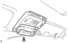
15. INSTALL OVERHEAD CONSOLE BOX (a) Connect the connector. (b) Install the console box with the bolt. |
|
16. INSTALL VISOR HOLDER
(a) Install the 2 holders with the 2 screws.
17. INSTALL CENTER VISOR ASSEMBLY
(a) Install the visors with the 4 screws.
18. INSTALL VISOR ASSEMBLY
(a) Install the 2 visors with the 4 screws, and then connect the 2 connectors.
(b) Install the 2 caps.
19. INSTALL FRONT DOOR OPENING TRIM WEATHERSTRIP
20. INSTALL FRONT PILLAR GARNISH
(a) Install the 2 garnishes.
21. INSTALL ASSIST GRIP SUB-ASSEMBLY
(a) Install the 4 assist grips with the 8 screws, and then install the 8 assist grip plugs.
22. CONNECT CABLE TO NEGATIVE BATTERY TERMINAL
23. PERFORM INITIALIZATION
(a)
Perform initialization
.
NOTICE:
Certain systems needs to be initialized after disconnecting and reconnecting the cable from the negative (-) battery terminal.

|

|