Last Modified: 6-7-2017 6.8:8.0.40 Doc ID: RM000001A8H000X
Model Year Start: 2006 Model: Land Cruiser Prod Date Range: [05/2005 -           ]
Title: AUDIO / VISUAL: AUDIO AND VISUAL SYSTEM: ON-VEHICLE INSPECTION; 2006 MY Land Cruiser [05/2005 -        ]

ON-VEHICLE INSPECTION

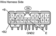
1. CHECK STEREO COMPONENT AMPLIFIER CIRCUIT

(a) Disconnect the S6 amplifier connector.

(b) Measure the resistance of the wire harness side connector.

Standard resistance:

Tester Connection

Specified Condition

S6-12 (E) - Body ground

Below 1 Ω

S6-13 (GND2) - Body ground

Below 1 Ω

(c) Measure the voltage of the wire harness side connector.

Standard voltage:

Tester Connection

Specified Condition

S6-7 (+B) - Body ground

10 to 14 V

S6-16 (+B2) - Body ground

10 to 14 V

  • If the results are not as specified, there may be a malfunction on the wire harness side.

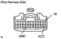
2. CHECK STEREO COMPONENT CONTROLLER ASSEMBLY CIRCUIT

(a) Disconnect the R39 controller connector.

(b) Measure the resistance of the wire harness side connector.

Standard resistance:

Tester Connection

Specified Condition

R39-17 (GND) - Body ground

Below 1 Ω

(c) Measure the voltage of the wire harness side connector.

Standard voltage:

Tester Connection

Condition

Specified Condition

R39-24 (ACC) - Body ground

Ignition switch OFF, radio receiver switch ON

Below 1 V

R39-24 (ACC) - Body ground

Ignition switch ACC or ON, radio receiver switch ON

10 to 14 V

R39-12 (+B) - Body ground

Always

10 to 14 V

  • If the results are not as specified, there may be a malfunction on the wire harness side.

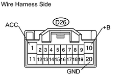
3. CHECK DISC PLAYER CHANGER CIRCUIT (w/ NAVIGATION SYSTEM)

(a) Disconnect the D26 changer connector.

(b) Measure the resistance of the wire harness side connector.

Standard resistance:

Tester Connection

Specified Condition

D26-20 (GND) - Body ground

Below 1 Ω

(c) Measure the voltage of the wire harness side connector.

Standard voltage:

Tester Connection

Condition

Specified Condition

D26-1 (ACC) - Body ground

Ignition switch OFF

Below 1 V

D26-1 (ACC) - Body ground

Ignition switch ACC or ON

10 to 14 V

D26-10 (+B) - Body ground

Always

10 to 14 V

  • If the results are not as specified, there may be a malfunction on the wire harness side.

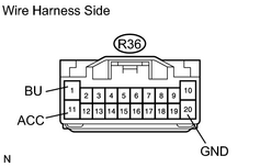
4. CHECK RADIO RECEIVER ASSEMBLY CIRCUIT

(a) Disconnect the R36 receiver connector.

(b) Measure the resistance of the wire harness side connector.

Standard resistance:

Tester Connection

Specified Condition

R36-20 (GND) - Body ground

Below 1 Ω

(c) Measure the voltage of the wire harness side connector.

Standard voltage:

Tester Connection

Condition

Specified Condition

R36-1 (BU) - Body ground

Always

10 to 14 V

R36-11 (ACC) - Body ground

Ignition switch OFF

Below 1 V

R36-11 (ACC) - Body ground

Ignition switch ON

10 to 14 V

  • If the results are not as specified, there may be a malfunction on the wire harness side.

HINT:

Check the wire harness between radio receiver assembly and DVD changer, between radio receiver assembly and stereo component amplifier.

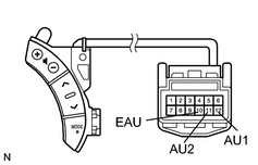
5. CHECK STEERING PAD SWITCH

(a) Disconnect the C18 switch connector.

(b) Measure the resistance of the switch.

Standard resistance:

Tester Connection

Condition

Specified Condition

C18-12 (AU1) - C18-10 (EAU)

Not pushed

Approx. 100 kΩ

C18-12 (AU1) - C18-10 (EAU)

SEEK+ switch pushed

Below 1 Ω

C18-12 (AU1) - C18-10 (EAU)

SEEK- switch pushed

Approx. 0.3 kΩ

C18-12 (AU1) - C18-10 (EAU)

VOL+ switch pushed

Approx. 1 kΩ

C18-12 (AU1) - C18-10 (EAU)

VOL- switch pushed

Approx. 3.2 kΩ

C18-11 (AU2) - C18-10 (EAU)

Not pushed

Approx. 100 kΩ

C18-11 (AU2) - C18-10 (EAU)

MODE switch pushed

Below 1 Ω

  • If the result is not as specified, the switch may have a malfunction.