| Last Modified: 6-7-2017 | 6.8:8.0.40 | Doc ID: RM000001AI3000X |
| Model Year Start: 2006 | Model: Land Cruiser | Prod Date Range: [05/2005 - ] |
| Title: NAVIGATION: NAVIGATION SYSTEM: Speaker Circuit; 2006 MY Land Cruiser [05/2005 - ] | ||
|
Speaker Circuit |
DESCRIPTION
This circuit is used when the voice guidance in the navigation system is on.
WIRING DIAGRAM
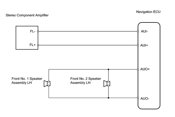
INSPECTION PROCEDURE
PROCEDURE
|
1. |
INSPECT APPARATUS |
(a) Choose the apparatus to be inspected.
Result:
|
Result |
Proceed to |
|---|---|
|
Front No. 1 speaker assembly LH |
A |
|
Front No. 2 speaker assembly LH |
B |
|
Front No. 1 and No. 2 speaker assembly |
C |
| B |

|
| C |
|
|

|
2. |
INSPECT FRONT NO. 1 SPEAKER ASSEMBLY LH |
(a) Disconnect the F8 speaker connector.
(b) Measure the resistance of the speaker.
Standard resistance:
|
Tester Connection |
Specified Condition |
|---|---|
|
1 - 2 |
Standard models: Approx. 2 Ω |
NOTICE:
The speaker should not be removed for checking.
| NG |
|
|
|
3. |
CHECK WIRE HARNESS (FRONT NO. 1 SPEAKER LH - FRONT NO. 2 SPEAKER LH AND BODY GROUND) |
|
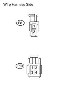
(a) Disconnect the F8 and T13 speaker connectors. (b) Measure the resistance of the wire harness side connector. Standard resistance:
|
|
| NG |
|
| OK |
|
PROCEED TO NEXT CIRCUIT INSPECTION SHOWN IN PROBLEM SYMPTOMS TABLE |
|
4. |
CHECK WIRE HARNESS (NAVIGATION ECU - STEREO COMPONENT AMPLIFIER ASSEMBLY) |
|
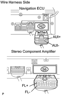
(a) Disconnect the N2 ECU connector. (b) Disconnect the S6 amplifier connector. (c) Measure the resistance of the wire harness side connectors. Standard resistance:
|
|
| NG |
|
|
|
5. |
INSPECT STEREO COMPONENT AMPLIFIER ASSEMBLY |
|
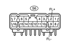
(a) Using an oscilloscope, check the signal waveform between the terminals according to the conditions, shown in the chart. OK:
|
|
| NG |
|
| OK |
|
PROCEED TO NEXT CIRCUIT INSPECTION SHOWN IN PROBLEM SYMPTOMS TABLE |

|

|