| Last Modified: 6-7-2017 | 6.8:8.0.40 | Doc ID: RM000001B6E001X |
| Model Year Start: 2006 | Model: Land Cruiser | Prod Date Range: [05/2005 - ] |
| Title: WINDSHIELD / WINDOWGLASS: POWER WINDOW CONTROL SYSTEM: TERMINALS OF ECU; 2006 MY Land Cruiser [05/2005 - ] | ||
TERMINALS OF ECU
1. CHECK POWER WINDOW REGULATOR MASTER SWITCH ASSEMBLY
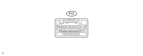
(a) Measure the voltage of the switch connector.
|
Symbols (Terminal No.) |
Wiring Color |
Condition |
Specified Condition |
|---|---|---|---|
|
GND (P12-2) - Body ground |
W-B - Body ground |
Always |
Below 1 V |
|
UP (P12-1) - GND (P12-2) |
Y - W-B |
Driver side power window does not operate |
Below 1 V |
|
Driver side power window moves upward |
10 to 14 V |
||
|
KL (P12-4) - KEYE (P12-3) |
L-W - W-B |
Door key lock and unlock switch is in LOCK position |
Below 1 V |
|
Door key lock and unlock switch is in OFF position |
10 to 14 V |
||
|
LMT (P12-5) - SGND (P12-13) |
L-Y - BR-B |
Except window full-close position |
Below 1 V |
|
Window full-close position |
10 to 14 V |
||
|
WLSW (P12-6) - GND (P12-2) |
Y-B - W-B |
Window lock switch OFF |
10 to 14 V |
|
Window lock switch ON |
Below 1 V |
||
|
MPX1 (P12-7) |
B |
Multiplex communication circuit |
- |
|
CPUB (P12-9) - GND (P12-2) |
L-W - W-B |
Always |
10 to 14 V |
|
BDR (P12-10) - GND (P12-2) |
L - W-B |
Always |
10 to 14 V |
|
DN (P12-11) - GND (P12-2) |
G - W-B |
Driver side power window does not operate |
Below 1 V |
|
Driver side power window moves downward |
10 to 14 V |
||
|
KUL (P12-14) - KEYE (P12-3) |
G-B - W-B |
Door key lock and unlock switch is in OFF position |
10 to 14 V |
|
Door key lock and unlock switch is in UNLOCK position |
Below 1 V |
||
|
PLS (P12-15) - SGND (P12-13) |
L-W - BR-B |
During power window operation |
Pulse generation |
|
Power window is not operated (pulse switch ON) |
Below 1 V |
||
|
Power window is not operated (pulse switch OFF) |
10 to 14 V |
||
|
LSWD (P12-16) - KEYE (P12-3) |
L-B - W-B |
Driver door lock position switch ON |
10 to 14 V |
|
Driver door lock position switch OFF |
Below 1 V |
||
|
SIG (P12-20) - GND (P12-2) |
B-W - W-B |
Ignition switch ON |
10 to 14 V |
- If the result is not as specified, the switch may have a malfunction.
2. CHECK FRONT POWER WINDOW REGULATOR SWITCH ASSEMBLY RH

(a) Measure the voltage of the switch connector.
|
Symbols (Terminal No.) |
Wiring Color |
Condition |
Specified Condition |
|---|---|---|---|
|
GND (P18-7) - Body ground |
W-B - Body ground |
Always |
Below 1 V |
|
DN (P18-1) - GND (P18-7) |
G - W-B |
Front passenger side power window does not operate |
Below 1 V |
|
Front passenger side power window moves downward |
10 to 14 V |
||
|
LMT (P18-3) - SGND (P18-5) |
L-Y - BR-B |
Except window full-close position |
Below 1 V |
|
Window full-close position |
10 to 14 V |
||
|
PLS (P18-4) - SGND (P18-5) |
L-W - BR-B |
During power window operation |
Below 1 V |
|
Power window is not operated (pulse switch ON) |
10 to 14 V |
||
|
Power window is not operated (pulse switch OFF) |
Below 1 V |
||
|
UP (P18-6) - GND (P18-7) |
Y - W-B |
Front passenger side power window is not operating |
Below 1 V |
|
Front passenger side power window is moving upward |
10 to 14 V |
||
|
MPX1 (P18-8) |
W |
Multiplex communication circuit |
- |
|
SEL1 (P18-9) - GND (P18-7) |
W-B - W-B |
Always |
Below 1 V |
|
PCT (P18-11) - GND (P18-7) |
Y-B - W-B |
Ignition switch ON, power window lock switch OFF |
Below 1 V |
|
Ignition switch ON, power window lock switch ON |
10 to 14 V |
||
|
BDR (P18-12) - GND (P18-7) |
L - W-B |
Always |
10 to 14 V |
- If the result is not as specified, the switch may have a malfunction.
3. CHECK REAR POWER WINDOW REGULATOR SWITCH ASSEMBLY LH

(a) Measure the voltage of the switch connector.
|
Symbols (Terminal No.) |
Wiring Color |
Condition |
Specified Condition |
|---|---|---|---|
|
GND (P19-7) - Body ground |
W-B - Body ground |
Always |
Below 1 V |
|
DN (P19-1) - GND (P19-7) |
G - W-B |
Rear power window LH does not operate |
Below 1 V |
|
Rear power window LH moves downward |
10 to 14 V |
||
|
LMT (P19-3) - SGND (P19-5) |
L-Y - BR-B |
Except window full-closed position |
Below 1 V |
|
Window full-closed position |
10 to 14 V |
||
|
PLS (P19-4) - SGND (P19-5) |
L-W - BR-B |
During power window operation |
Below 1 V |
|
Power window is not operated (pulse switch ON) |
10 to 14 V |
||
|
Power window is not operated (pulse switch OFF) |
Below 1 V |
||
|
UP (P19-6) - GND (P19-7) |
Y - W-B |
Rear power window LH is not operating |
Below 1 V |
|
Rear power window LH is moving upward |
10 to 14 V |
||
|
MPX1 (P19-8) |
W |
Multiplex communication circuit |
- |
|
SEL2 (P19-10) - GND (P19-7) |
W-B - W-B |
Always |
Below 1 V |
|
PCTI (P19-11) - GND (P19-7) |
Y-B - W-B |
Ignition switch ON, power window lock switch OFF |
Below 1 V |
|
Ignition switch ON, power window lock switch ON |
10 to 14 V |
||
|
BDR (P19-12) - GND (P19-7) |
L - W-B |
Always |
10 to 14 V |
- If the result is not as specified, the switch may have a malfunction.
4. CHECK REAR POWER WINDOW REGULATOR SWITCH ASSEMBLY RH

(a) Measure the voltage of the switch connector.
|
Symbols (Terminal No.) |
Wiring Color |
Condition |
Specified Condition |
|---|---|---|---|
|
GND (P20-7) - Body ground |
W-B - Body ground |
Always |
Below 1 V |
|
DN (P20-1) - GND (P20-7) |
G - W-B |
Rear power window RH does not operate |
Below 1 V |
|
Rear power window RH moves downward |
10 to 14 V |
||
|
LMT (P20-3) - SGND (P20-5) |
L-Y - BR-B |
Except window full-closed position |
Below 1 V |
|
Window full-closed position |
10 to 14 V |
||
|
PLS (P20-4) - SGND (P20-5) |
L-W - BR-B |
During power window operation |
Below 1 V |
|
Power window is not operated (pulse switch ON) |
10 to 14 V |
||
|
Power window is not operated (pulse switch OFF) |
Below 1 V |
||
|
UP (P20-6) - GND (P20-7) |
Y - W-B |
Rear power window RH is not operating |
Below 1 V |
|
Rear power window RH is moving upward |
10 to 14 V |
||
|
MPX1 (P20-8) |
W |
Multiplex communication circuit |
- |
|
PCTI (P20-11) - GND (P20-7) |
Y-B - W-B |
Ignition switch ON, power window lock switch OFF |
Below 1 V |
|
Ignition switch ON, power window lock switch ON |
10 to 14 V |
||
|
BDR (P20-12) - GND (P20-7) |
L - W-B |
Always |
10 to 14 V |
- If the result is not as specified, the switch may have a malfunction.

|

|