| Last Modified: 6-7-2017 | 6.8:8.0.40 | Doc ID: RM000001A5F006X |
| Model Year Start: 2007 | Model: Land Cruiser | Prod Date Range: [08/2006 - ] |
| Title: BRAKE CONTROL: VEHICLE STABILITY CONTROL SYSTEM: TERMINALS OF ECU; 2007 MY Land Cruiser [08/2006 - ] | ||
TERMINALS OF ECU
1. CHECK SKID CONTROL ECU
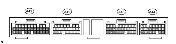
(a) Measure the voltage and resistance of the connectors.
|
Symbols (Terminal No.) |
Wiring Color |
Terminal Description |
Condition |
Specified Condition |
|---|---|---|---|---|
|
SA1 (A41-2) - GND (A41-6, 31, A42-8, 17) |
G - W-B |
Front RH ABS switching solenoid output |
Ignition switch ON, ABS warning light OFF |
10 to 14 V |
|
SA2 (A41-3) - GND (A41-6, 31, A42-8, 17) |
B - W-B |
Front LH ABS switching solenoid output |
Ignition switch ON, ABS warning light OFF |
10 to 14 V |
|
SA3 (A41-4) - GND (A41-6, 31, A42-8, 17) |
G-W - W-B |
Rear ABS switching solenoid output |
Ignition switch ON, ABS warning light OFF |
10 to 14 V |
|
STR (A41-5) - GND (A41-6, 31, A42-8, 17) |
G-Y - W-B |
VSC switching solenoid output |
Ignition switch ON, ABS warning light OFF |
10 to 14 V |
|
SFLR (A41-7) - GND (A41-6, 31, A42-8, 17) |
B-Y - -W-B |
Front left decompression solenoid output |
Ignition switch ON, ABS warning light OFF |
10 to 14 V |
|
SRRH (A41-8) - GND (A41-6, 31, A42-8, 17) |
W - W-B |
Rear right holding solenoid output |
Ignition switch ON, ABS warning light OFF |
10 to 14 V |
|
SRRR (A41-9) - GND (A41-6, 31, A42-8, 17) |
B-O - W-B |
Rear right decompression solenoid output |
Ignition switch ON, ABS warning light OFF |
10 to 14 V |
|
VCM (A41-10) - E2 (A41-12) |
B - W |
Master cylinder pressure sensor power source |
Ignition switch ON |
4.5 to 5.5 V |
|
PH (A41-11) - GND (A41-6, 31, A42-8, 17) |
O - W-B |
Pressure switch (high) input |
Ignition switch ON, pressure switch (PH) ON |
Below 1 V |
|
PH (A41-11) - GND (A41-6, 31, A42-8, 17) |
O - W-B |
Pressure switch (high) input |
Ignition switch ON, pressure switch (PH) OFF |
5 to 8 V |
|
FR+ (A41-14) - FR- (A41-13) |
L-P |
Front right wheel speed sensor input |
Ignition switch ON, slowly turn right front wheel |
Pulse generation |
|
FL+ (A41-16) - FL- (A41-15) |
R-G |
Front left wheel speed sensor input |
Ignition switch ON, slowly turn left front wheel |
Pulse generation |
|
SR (A41-19) - R1+ (A41-1) |
G-Y - P |
Solenoid relay output |
Ignition switch ON, ABS warning light OFF |
10 to 14 V |
|
SFLH (A41-21) - GND (A41-6, 31, A42-8, 17) |
Y - W-B |
Front left holding solenoid output |
Ignition switch ON, ABS warning light OFF |
10 to 14 V |
|
PMC (A41-22) - E2 (A41-12) |
R-W |
Master cylinder pressure sensor input |
Ignition switch ON, stop light switch OFF |
0.3 to 0.7 V |
|
E2 (A41-12) - GND (A41-6, 31, A42-8, 17) |
W - W-B |
ACC pressure sensor ground |
Ignition switch OFF |
Below 1 Ω |
|
MTT (A41-27) - GND (A41-6, 31, A42-8, 17) |
B-R - W-B |
Motor test input |
Ignition switch ON (Motor relay is OFF) |
Below 1.5 V |
|
MT+ (A41-28) - MT- (A41-18) |
L - GR |
Motor relay input |
Ignition switch ON |
Below 1.5 V |
|
MR1 (A41-29) - R1+ (A41-1) |
R - P |
Motor relay output 1 |
Ignition switch ON, hydraulic brake booster pump motor ON |
10 to 14 V |
|
WA (A42-1) - GND (A41-6, 31, A42-8, 17) |
R-L - W-B |
ABS warning light output |
Ignition switch ON, ABS warning light OFF |
Below 2.0 V |
|
BZ (A42-2) - GND (A41-6, 31, A42-8, 17) |
L - W-B |
VSC buzzer output |
Ignition switch ON, VSC buzzer is sounded |
Below 1.5 V |
|
D/G (A42-3) - GND (A41-6, 31, A42-8, 17) |
V-W - W-B |
Diagnostics tester communication line |
Ignition switch ON |
10 to 14 V |
|
P (A42-5) - GND (A41-6, 31, A42-8, 17) |
G-W - W-B |
Shift position indicator "P" input |
Ignition switch ON, shift lever is in P position |
10 to 14 V |
|
IG1 (A42-6) - GND (A41-6, 31, A42-8, 17) |
B-W - W-B |
IG1 power source |
Ignition switch ON |
10 to 14 V |
|
STP (A42-10) - GND (A41-6, 31, A42-8, 17) |
G-W - W-B |
Stop light switch input |
Stop light switch OFF |
Below 1.5 V |
|
STP (A42-10) - GND (A41-6, 31, A42-8, 17) |
G-W - W-B |
Stop light switch input |
Stop light switch ON |
10 to 14 V |
|
TC (A42-11) - GND (A41-6, 31, A42-8, 17) |
P-B - W-B |
Terminal TC of DLC3 |
Ignition switch OFF |
Below 1 V |
|
TC (A42-11) - GND (A41-6, 31, A42-8, 17) |
P-B - W-B |
Terminal TC of DLC3 |
Ignition switch ON |
10 to 14 V |
|
TS (A42-12) - GND (A41-6, 31, A42-8, 17) |
W - W-B |
Terminal TS of DLC3 |
Ignition switch OFF |
Below 1 V |
|
TS (A42-12) - GND (A41-6, 31, A42-8, 17) |
W - W-B |
Terminal TS of DLC3 |
Ignition switch ON |
10 to 14 V |
|
PKB (A42-13) - GND (A41-6, 31, A42-8, 17) |
R-W - W-B |
Parking brake switch input |
Ignition switch ON, parking brake switch ON |
Below 1.5 V |
|
PKB (A42-13) - GND (A41-6, 31, A42-8, 17) |
R-W - W-B |
Parking brake switch input |
Ignition switch ON, parking brake switch OFF |
10 to 14 V |
|
ENG+ (A42-14) - ENG- (A42-22) |
R - G |
Translate ECU communication input |
Ignition switch ON |
Pulse generation |
|
RL+ (A42-18) - RL- (A42-19) |
R - G |
Rear left wheel speed sensor input |
Ignition switch ON, slowly turn left rear wheel |
Pulse generation |
|
RR+ (A42-20) - RR- (A42-21) |
B - W |
Rear right wheel speed sensor input |
Ignition switch ON, slowly turn right rear wheel |
Pulse generation |
|
TRC+ (A42-24) - TRC- (A42-16) |
Y - L |
Translate ECU communication output |
Ignition switch ON |
Pulse generation |
|
EXI2 (A43-2) - GND (A41-6, 31, A42-8, 17) |
B-L - W-B |
L4 switch input |
Ignition switch ON, L4 switch ON |
8 to 14 V |
|
EXI2 (A43-2) - GND (A41-6, 31, A42-8, 17) |
B-L - W-B |
L4 switch input |
Ignition switch ON, L4 switch OFF |
Below 1.5 V |
|
EXI (A43-3) - GND (A41-6, 31, A42-8, 17) |
P-B - W-B |
Center differential lock switch input |
Ignition switch ON, differential lock switch ON |
Below 1.5 V |
|
EXI (A43-3) - GND (A41-6, 31, A42-8, 17) |
P-B - W-B |
Center differential lock switch input |
Ignition switch ON, differential lock switch OFF |
10 to 14 V |
|
VSCW (A43-4) - GND (A41-6, 31, A42-8, 17) |
L-W - W-B |
VSC TRAC warning light output |
Ignition switch ON, VSC TRAC warning light ON |
Below 2.0 V |
|
VSCW (A43-4) - GND (A41-6, 31, A42-8, 17) |
L-W - W-B |
VSC TRAC warning light output |
Ignition switch ON, VSC TRAC warning light OFF |
10 to 14 V |
|
BRL (A43-5) - GND (A41-6, 31, A42-8, 17) |
Y-G - W-B |
BRAKE warning light output |
Ignition ON, BRAKE warning light ON |
10 to 14 V |
|
BRL (A43-5) - GND (A41-6, 31, A42-8, 17) |
Y-G - W-B |
BRAKE warning light output |
Ignition ON, BRAKE warning light OFF |
Below 2.0 V |
|
IND (A43-6) - GND (A41-6, 31, A42-8, 17) |
L-B - W-B |
SLIP indicator light input |
Ignition switch ON, SLIP indicator light ON |
Below 2.0 V |
|
IND (A43-6) - GND (A41-6, 31, A42-8, 17) |
L-B - W-B |
SLIP indicator light input |
Ignition switch ON, SLIP indicator light OFF |
10 to 14 V |
|
WT (A43-7) - GND (A41-6, 31, A42-8, 17) |
L-R - W-B |
VSC OFF indicator light input |
Ignition switch ON, DSC OFF indicator light ON |
Below 2.0 V |
|
WT (A43-7) - GND (A41-6, 31, A42-8, 17) |
L-R - W-B |
VSC OFF indicator light input |
Ignition switch ON, VSC OFF indicator light OFF |
10 to 14 V |
|
VYS (A43-9) - GYAW (A43-27) |
B-R |
Yaw rate sensor power supply |
Ignition switch ON |
4.5 to 5.5 V |
|
GL2 (A43-10) - GYAW (A43-27) |
Y - R |
Decelerate sensor input2 |
Ignition switch ON, vehicle is on level surface |
2.0 to 3.0 V |
|
SS1+ (A43-14) - SS1- (A43-23) |
W - G |
Steering sensor (+) input |
Engine idling, slowly turn steering wheel |
Pulse generation |
|
INFR (A43-15) - GND (A41-6, 31, A42-8, 17) |
B-R - W-B |
VSC TRAC indicator light input |
Ignition switch ON, VSC TRAC indicator light ON |
Below 1.5 V |
|
INFR (A43-15) - GND (A41-6, 31, A42-8, 17) |
B-R - W-B |
VSC TRAC indicator light input |
Ignition switch ON, VSC TRAC indicator light OFF |
10 to 14 V |
|
YD (A43-19) - GND (A41-6, 31, A42-8, 17) |
L - W-B |
Yaw rate signal diagnosis output |
Approximately 1 sec. after ignition switch ON |
4.5 to 5.3 V |
|
GL1 (A43-22) - GYAW (A43-27) |
G - R |
Decelerate sensor input1 |
Ignition switch ON, vehicle is on level surface |
2.0 to 3.0 V |
|
GYAW (A43-27) - GND (A41-6, 31, A42-8, 17) |
R - W-B |
Yaw rate sensor ground |
Ignition switch OFF |
Below 1 Ω |
|
YAW (A43-28) - GYAW (A43-27) |
W - R |
Yaw rate sensor input |
Ignition switch ON, vehicle is in stationary condition |
2 to 3 V |
|
SRLR (A44-1) - GND (A41-6, 31, A42-8, 17) |
R-G - W-B |
Rear left decompression solenoid output |
Ignition switch ON, ABS warning light OFF |
10 to 14 V |
|
MR2 (A44-2) - R2+ (A44-3) |
Y-B - W-L |
Motor relay output |
Ignition switch ON, hydraulic brake booster pump motor stops |
10 to 14 V |
|
AST (A44-6) - GND (A41-6, 31, A42-8, 17) |
R-Y - W-B |
Solenoid relay test input |
Ignition switch ON, ABS warning light OFF |
10 to 14 V |
|
SRLH (A44-7) - GND (A41-6, 31, A42-8, 17) |
R-W - W-B |
Rear left holding solenoid output |
Ignition switch ON, ABS warning light OFF |
10 to 14 V |
|
SFRR (A44-8) - GND (A41-6, 31, A42-8, 17) |
B-W - W-B |
Front right decompression solenoid output |
Ignition switch ON, ABS warning light OFF |
10 to 14 V |
|
PL (A44-9) - GND (A41-6, 31, A42-8, 17) |
W - W-B |
Pressure switch (Low) input |
Ignition switch ON, pressure switch (PL) ON |
3 to 5 V |
|
PL (A44-9) - GND (A41-6, 31, A42-8, 17) |
W - W-B |
Pressure switch (Low) input |
Ignition switch ON, pressure switch (PL) OFF |
7 to 11 V |
|
SFRH (A44-16) - GND (A41-6, 31, A42-8, 17) |
LG - W-B |
Front right holding solenoid output |
Ignition switch ON, ABS warning light OFF |
10 to 14 V |
|
TRIG (A44-20) - GND (A41-6, 31, A42-8, 17) |
L-R - W-B |
Steering sensor trigger output |
Ignition switch ON, ABS warning light OFF |
10 to 14 V |
|
+BO (A44-21) - GND (A41-6, 31, A42-8, 17) |
LG - W-B |
Steering sensor power source |
Ignition switch ON, ABS warning light OFF |
10 to 14 V |
|
IG2 (A44-22) - GND (A41-6, 31, A42-8, 17) |
B-R - W-B |
IG2 power source |
Ignition switch ON |
10 to 14 V |
2. CHECK TRANSLATE ECU
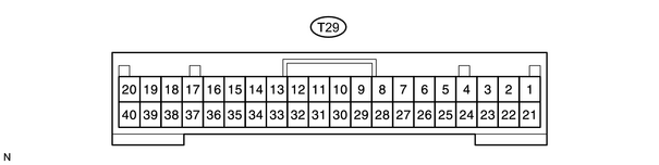
(a) Measure the voltage of the connector.
|
Symbols (Terminal No.) |
Wiring Color |
Terminal Description |
Condition |
Specified Condition |
|---|---|---|---|---|
|
IG1 (T29-1) - GND (T29-40) |
B-W - W-B |
IG1 power source |
Ignition switch ON |
10 to 14 V |
|
CANH (T29-7) - CANL (T29-10) |
R - W |
Multiplex communication line |
Ignition switch ON |
Pulse generation |
|
ENG+ (T29-14) - ENG-(T29-15) |
R - G |
ECM communication line |
Ignition switch ON |
Pulse generation |
|
TRC+ (T29-16) - TRC- (T29-17) |
Y - L |
ECM communication line |
Ignition switch ON |
Pulse generation |

|

|