DISASSEMBLY
Removal / installation · Vehicles built from Aug 2013
| 1. REMOVE AUTOMATIC TRANSMISSION CASE O-RING |

Remove the O-ring from the oil pump assembly.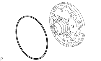

| 2. FIX OIL PUMP ASSEMBLY |
Place the oil pump body on the torque converter clutch.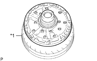
Text in Illustration *1
Torque Converter Clutch
| 3. REMOVE CLUTCH DRUM OIL SEAL RING |
Remove the 3 oil seal rings.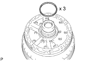
| 4. REMOVE STATOR SHAFT ASSEMBLY |
Remove the 14 bolts and stator shaft from the oil pump body.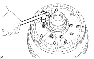
| 5. REMOVE FRONT OIL PUMP BODY O-RING |
Remove the O-ring from the oil pump body.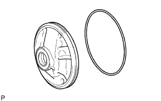
Remove the oil pump body from the torque converter clutch.
| 6. INSPECT FRONT OIL PUMP BODY SUB-ASSEMBLY |
Using a dial indicator, measure the inside diameter of the oil pump body bush.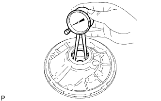
- Maximum inside diameter:
- 38.188 mm (1.50 in.)
- If the inside diameter is more than the maximum, replace the oil pump body sub-assembly.
| 7. INSPECT STATOR SHAFT ASSEMBLY |
Using a dial indicator, measure the inside diameter of the stator shaft bush.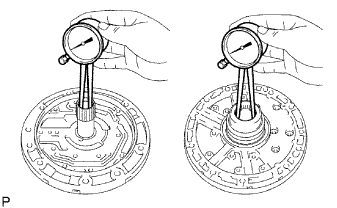
- Maximum inside diameter:
- Front side:
- 21.577 mm (0.849 in.)
- Rear side:
- 32.08 mm (1.26 in.)
- If the inside diameter is more than the maximum, replace the stator shaft assembly.
| 8. INSPECT CLEARANCE OF OIL PUMP ASSEMBLY |
Push the driven gear to one side of the body.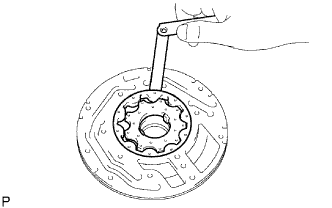
Using a feeler gauge, measure the body clearance.
- Standard body clearance:
- 0.10 to 0.17 mm (0.00394 to 0.00669 in.)
- Maximum body clearance:
- 0.17 mm (0.00669 in.)
- If the body clearance is more than the maximum, replace the drive gear, driven gear or pump body assembly. Replace the part or parts determined to be the most likely cause of the problem.
Using a feeler gauge, measure the tip clearance between the driven gear teeth and drive gear teeth.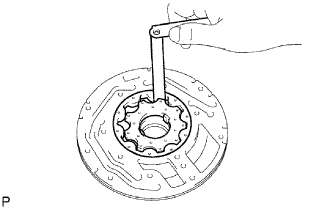
- Standard tip clearance:
- 0.070 to 0.150 mm (0.00276 to 0.00591 in.)
- Maximum tip clearance:
- 0.150 mm (0.00591 in.)
- If the tip clearance is more than the maximum, replace the drive gear, driven gear or pump body assembly. Replace the part or parts determined to be the most likely cause of the problem.
Using a steel straightedge and feeler gauge, measure the side clearance of both gears.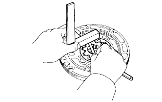
- Standard side clearance:
- 0.02 to 0.05 mm (0.000787 to 0.00197 in.)
- Maximum side clearance:
- 0.05 mm (0.00197 in.)
- HINT:
- There are 5 different drive and driven gear thicknesses.
- Drive and Driven Gear Thickness:
Mark
Thickness
0
10.74 to 10.749 mm (0.42283 to 0.42319 in.)
1
10.75 to 10.759 mm (0.42323 to 0.42358 in.)
2
10.76 to 10.77 mm (0.42362 to 0.42401 in.)
3
10.771 to 10.78 mm (0.42405 to 0.42441 in.)
4
10.781 to 10.79 mm (0.42445 to 0.42480 in.)
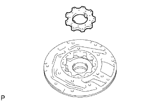
| 9. REMOVE FRONT OIL PUMP DRIVE GEAR |
 |
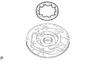
| 10. REMOVE FRONT OIL PUMP DRIVEN GEAR |
 |
| 11. REMOVE FRONT OIL PUMP OIL SEAL |
Using a screwdriver, pry out the oil seal.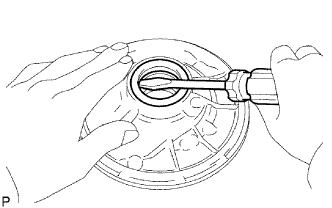
- NOTICE:
- Be careful not to damage the bushing or oil pump body.