TERMINALS OF ECM
System information · Vehicles built from Aug 2013
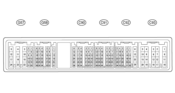

- HINT:
- Each ECM terminal's standard voltage is shown in the table below.
- In the table, first follow the information under "Condition". Look under "Terminal No. (Symbol)" for the terminals to be inspected. The standard voltage between the terminals is shown under "Specified Condition".
- Use the illustration above as a reference for the ECM terminals.
| Terminal No. (Symbol) |
Wiring Color |
Terminal Description |
Condition |
Specified Condition |
| G57-23 (BATT) - C93-1 (E1) |
L - BR |
Battery (for measuring the battery voltage and for the ECM memory) |
Always |
11 to 14 V |
| G58-24 (IGSW) - C93-1 (E1) |
W - BR |
Engine switch |
Engine switch on (IG) |
11 to 14 V |
| G57-24 (+B) - C93-1 (E1) |
W - BR |
Power source of ECM |
Engine switch on (IG) |
11 to 14 V |
| G57-17 (+B2) - C93-1 (E1) |
W - BR |
Power source of ECM |
Engine switch on (IG) |
11 to 14 V |
| G58-11 (MREL) - C93-1 (E1) |
V - BR |
EFI relay |
Engine switch on (IG) |
11 to 14 V |
| G58-11 (MREL) - C93-1 (E1) |
V - BR |
EFI relay |
10 seconds elapsed after engine switch off |
0 to 1.5 V |
| G58-6 (VCPA) - G58-5 (EPA) |
LG - P |
Power source of accelerator pedal position sensor (for VPA) |
Engine switch on (IG) |
4.5 to 5.5 V |
| G58-4 (VCP2) - G58-3 (EPA2) |
R - W |
Power source of accelerator pedal position sensor (for VPA2) |
Engine switch on (IG) |
4.5 to 5.5 V |
| G57-2 (VPA) - G58-5 (EPA) |
L - P |
Accelerator pedal position sensor (for engine control) |
Engine switch on (IG), accelerator pedal fully released |
0.5 to 1.1 V |
| G57-2 (VPA) - G58-5 (EPA) |
L - P |
Accelerator pedal position sensor (for engine control) |
Engine switch on (IG), accelerator pedal fully depressed |
3.0 to 4.6 V |
| G57-1 (VPA2) - G58-3 (EPA2) |
GR - W |
Accelerator pedal position sensor (for sensor malfunction detection) |
Engine switch on (IG), accelerator pedal fully released |
0.9 to 2.3 V |
| G57-1 (VPA2) - G58-3 (EPA2) |
GR - W |
Accelerator pedal position sensor (for sensor malfunction detection) |
Engine switch on (IG), accelerator pedal fully depressed |
3.4 to 5.0 V |
| C90-17 (VG) - C90-18 (EVG) |
W - B-W |
Mass air flow meter |
Idling |
Pulse generation |
| C90-6 (THA) - C90-12 (ETHA) |
Y-B - BR |
Intake air temperature sensor (built into mass air flow meter) |
Idling, intake air temperature at 20°C (68°F) |
0.5 to 3.4 V |
| C90-3 (THIA) - C90-9 (ETHI) |
B - BR |
Intake air temperature sensor (turbo) |
Idling, intake air temperature at 0 to 80°C (32 to 176°F) |
0.5 to 3.4 V |
| C90-5 (THW) - C90-11 (ETHW) |
R-L - BR |
Engine coolant temperature sensor |
Idling, engine coolant temperature at 80°C (176°F) |
0.2 to 1.0 V |
| C90-4 (THF) - C90-10 (ETHF) |
G-B - BR |
Fuel temperature sensor |
Engine switch on (IG) |
0.5 to 3.4 V |
| G57-6 (STA) - C93-1 (E1) |
W - BR |
Starter signal |
Cranking |
6.0 V or higher |
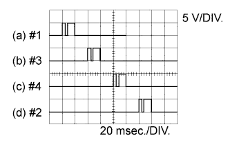
| C90-21 (#1) - C93-1 (E1) C90-22 (#2) - C93-1 (E1) C90-23 (#3) - C93-1 (E1) C90-24 (#4) - C93-1 (E1) |
B-W - BR L - BR R-L - BR Y - BR |
Injector assembly |
Idling |
Pulse generation (See waveform 2) |
| C92-13 (G+) - C92-14 (G-) |
G - R |
Camshaft position sensor |
Idling |
Pulse generation (See waveform 5) |
| C92-7 (NE+) - C92-8 (NE-) |
W - B |
Crankshaft position sensor |
Idling |
Pulse generation (See waveform 5) |
| G57-8 (STP) - C93-1 (E1) |
V - BR |
Stop light switch assembly |
Engine switch on (IG), brake pedal depressed |
7.5 to 14 V |
| G57-8 (STP) - C93-1 (E1) |
V - BR |
Stop light switch assembly |
Engine switch on (IG), brake pedal released |
0 to 1.5 V |
| G57-9 (ST1-) - C93-1 (E1) |
B - BR |
Stop light switch assembly (opposite to STP) |
Engine switch on (IG), brake pedal depressed |
0 to 1.5 V |
| G57-9 (ST1-) - C93-1 (E1) |
B - BR |
Stop light switch assembly (opposite to STP) |
Engine switch on (IG), brake pedal released |
7.5 to 14 V |
| C91-15 (CLSW)*1 - C93-1 (E1) |
B - BR |
Clutch switch assembly |
Engine switch on (IG), clutch pedal released |
8.5 to 14 V |
| G58-23 (TC) - C93-1 (E1) |
V - BR |
Terminal TC of DLC3 |
Engine switch on (IG) |
11 to 14 V |
| G57-19 (W) - C93-1 (E1) |
V - BR |
MIL |
MIL illuminated |
0 to 3 V |
| G57-19 (W) - C93-1 (E1) |
V - BR |
MIL |
MIL not illuminated |
11 to 14 V |
| G58-30 (SPD) - C93-1 (E1) |
R - BR |
Speed signal from combination meter assembly |
Engine switch on (IG), slowly wheel rotated |
Pulse generation (See waveform 9) |
| C91-12 (VCPM) - C91-16 (EPIM) |
R - B |
Power source of manifold absolute pressure sensor |
Engine switch on (IG) |
4.5 to 5.5 V |
| C91-5 (PIM) - C91-16 (EPIM) |
L-B - B |
Manifold absolute pressure sensor |
Negative pressure of 40 kPa (300 mmHg, 11.8 in.Hg) applied |
0.1 to 0.7 V |
| C91-5 (PIM) - C91-16 (EPIM) |
L-B - B |
Manifold absolute pressure sensor |
Same as atmospheric pressure |
0.8 to 1.5 V |
| C91-5 (PIM) - C91-16 (EPIM) |
L-B - B |
Manifold absolute pressure sensor |
Positive pressure of 170 kPa (1275 mmHg, 50.2 in.Hg) applied |
1.6 to 2.3 V |
| G58-12 (IREL) - C93-1 (E1) |
B - BR |
EDU relay |
Engine switch on (IG) |
0 to 1.5 V |
| G57-18 (TACH) - C93-1 (E1) |
P - BR |
Engine speed |
Idling |
Pulse generation |
| C90-14 (VCM) - C90-15 (E2M) |
Y-B - GR |
Power source of fuel pressure sensor (for PCR1) |
Engine switch on (IG) |
4.5 to 5.5 V |
| C90-13 (VCS) - C90-8 (E2S) |
LG - L |
Power source of fuel pressure sensor (for PCR2) |
Engine switch on (IG) |
4.5 to 5.5 V |
| C90-16 (PCR1) - C90-15 (E2M) |
R - GR |
Fuel pressure sensor (main) |
Idling |
1.8 to 2.1 V |
| C90-2 (PCR2) - C90-8 (E2S) |
Y - L |
Fuel pressure sensor (sub) |
Idling |
1.2 to 1.5 V |
| C91-23 (ALT) - C93-1 (E1) |
L - BR |
Generator assembly (Alternator) duty ratio |
Idling |
Pulse generation |
| C91-7 (PEX) - C91-14 (EPEX) |
L - G |
Differential pressure sensor |
Engine switch on (IG) |
0.4 to 4.8 V |
| C92-6 (HAF2) - C93-11 (E05) |
W - W-B |
Air fuel ratio sensor heater |
Engine switch on (IG) |
11 to 14 V |
| C92-2 (AF2+) - C93-11 (E05) |
L - W-B |
Air fuel ratio sensor |
Engine switch on (IG) |
2.0 to 2.5 V |
| C93-5 (FIV) - C93-1 (E1) |
W - BR |
Exhaust fuel addition injector |
Exhaust fuel addition injector operating |
Pulse generation |
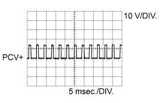
| C92-23 (PCV+) - C92-12 (PCV-) |
W - B |
Suction control valve |
Idling |
Pulse generation (See waveform 1) |
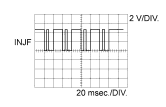
| C90-20 (INJF) - C93-1 (E1) |
BR - BR |
Injector driver |
Idling |
Pulse generation (See waveform 3) |
| C90-19 (PRD) - C93-1 (E1) |
B - BR |
Pressure discharge valve drive signal |
Engine warmed up, engine racing |
Pulse generation (See waveform 4) |
| C92-4 (RLFF) - C93-1 (E1) |
GR - BR |
Pressure discharge valve confirmation signal |
Engine warmed up, engine racing |
Pulse generation (See waveform 4) |
| C92-19 (IDLO) - C93-1 (E1) |
G - BR |
EDU |
Idling |
4 to 5.5 V |
| C92-25 (EOPV) - C93-1 (E1) |
B-R - BR |
Oil pressure switching valve |
Idling |
0 to 1.5 V |
| C93-15 (M+) - C93-1 (E1) |
W - BR |
DC motor (turbocharger sub-assembly) |
Idling |
Pulse generation (See waveform 6) |
| C93-14 (M-) - C93-1 (E1) |
B - BR |
DC motor (turbocharger sub-assembly) |
Idling |
Pulse generation (See waveform 7) |
| C91-11 (VNVC) - C91-10 (VNE2) |
W - L |
Power source of nozzle vane position sensor |
Engine switch on (IG) |
4.5 to 5.5 V |
| C91-6 (VNA) - C91-10 (VNE2) |
R - L |
Nozzle vane position sensor |
Engine switch on (IG) |
2.3 to 2.7 V |
| C91-8 (VCVL) - C91-9 (EVLU) |
R - W |
Power source of throttle position sensor |
Engine switch on (IG) |
4.5 to 5.5 V |
| C91-3 (VLU) - C91-9 (EVLU) |
LG - W |
Throttle position sensor |
Engine switch on (IG), throttle valve fully opened |
3.6 to 4.2 V |
| C91-3 (VLU) - C91-9 (EVLU) |
LG - W |
Throttle position sensor |
Engine switch on (IG), throttle valve fully closed |
0.4 to 1.0 V |
| C92-15 (LUSL) - C93-1 (E1) |
L-R - BR |
Diesel throttle duty signal |
Engine warmed up, racing engine |
Pulse generation (See waveform 8) |
| C91-13 (VCPX) - C91-14 (EPEX) |
L - G |
Power source of sensor (specific voltage) |
Engine switch on (IG) |
4.5 to 5.5 V |
| C90-1 (EGRA) - C90-7 (EEGL) |
R-Y - G |
EGR valve position sensor |
Engine switch on (IG) |
0.6 to 1.4 V |
| C93-6 (EGM+) - C93-8 (ME01) |
LG - W-B |
EGR valve duty signal |
Engine warmed up, idling |
Pulse generation |
| C93-7 (EGM-) - C93-8 (ME01) |
V - W-B |
EGR valve duty signal |
Engine warmed up, idling |
Pulse generation |
| C93-4 (ECBV) - C93-1 (E1) |
L-Y - BR |
Vacuum switching valve (for No. 1 EGR bypass valve) |
Vacuum switching valve assembly (for No. 1 EGR bypass valve) on |
0 to 1.5 V |
| Vacuum switching valve assembly (for No. 1 EGR bypass valve) off |
11 to 14 V |
|||
| G57-22 (ECB2) - C93-1 (E1) |
R - BR |
Vacuum switching valve (for No. 2 EGR bypass valve) |
Vacuum switching valve assembly (for No. 2 EGR bypass valve) on |
0 to 1.5 V |
| Vacuum switching valve assembly (for No. 2 EGR bypass valve) off |
11 to 14 V |
|||
| C91-4 (POP) - C91-14 (EPEX) |
P - G |
Oil pressure sender gauge assembly |
Engine running |
0.1 to 0.9 V |
| C92-17 (THCF) - C92-16 (ETCF) |
R-W - G-B |
Exhaust gas temperature sensor |
Engine warmed up, idling |
4.6 to 4.9 V |
| C92-5 (THCI) - C92-11 (ETCI) |
G-B - G-R |
No. 2 Exhaust gas temperature sensor |
Engine warmed up, idling |
4.6 to 4.9 V |
| C91-1 (THCO) - C91-2 (ETCO) |
B - R |
No. 3 Exhaust gas temperature sensor |
Engine warmed up, idling |
4.6 to 4.9 V |
| C93-2 (SCV) - C93-12 (E01) |
B-W - W-B |
Vacuum switching valve (for No. 1 swirl control valve) |
Idling |
0 to 1.5 V |
| Engine speed 2600 rpm or more |
11 to 14 V |
|||
| C93-3 (SCV2) - C93-12 (E01) |
L-B - W-B |
Vacuum switching valve (for No. 2 swirl control valve) |
Idling |
0 to 1.5 V |
| Engine speed 2,600 rpm or more |
11 to 14 V |
|||
| C92-20 (PSW) - C93-12 (E01) |
G - W-B |
Power steering oil pressure switch |
Steering wheel turned |
0 to 3 V |
| Steering wheel not turned |
11 to 14 V |
|||
| G57-10 (ACM) - C93-12 (E01) |
B - W-B |
Vacuum switching valve (for engine mounting) |
Idling |
0 to 1.5 V |
| G58-10 (AC1) - C93-12 (E01) |
LG - W-B |
A/C signal |
A/C switch on |
0 to 1.5 V |
| A/C switch off |
11 to 14 V |
|||
| G58-13 (ACT) - C93-12 (E01) |
R - W-B |
A/C signal |
Engine switch on (IG) |
11 to 14 V |
| A/C cut control on |
0 to 3 V |
|||
| C92-26 (NSW)*2 - C93-12 (E01) |
B - W-B |
Park/neutral position switch assembly |
Engine switch on (IG), shift lever in P or N |
Below 3 V |
| Engine switch on (IG), shift lever not in P and N |
11 to 14 V |
|||
| C91-15 (D)*2 - C93-12 (E01) |
G - W-B |
Park/neutral position switch assembly |
Engine switch on (IG), shift lever in D |
11 to 14 V |
| Engine switch on (IG), shift lever not in D |
Below 1 V |
|||
| G57-15 (FAN) - C93-12 (E01) |
GR - W-B |
FAN relay |
Engine switch on (IG) |
11 to 14 V |
| Idling with A/C on or High engine coolant temperature |
Below 1.5 V |
|||
| G58-36 (CANL) - C93-1 (E1) |
W - BR |
CAN communication line |
Engine switch on (IG) |
Pulse generation (See waveform 10) |
| G58-35 (CANH) - C93-1 (E1) |
LG - BR*3 R - BR*4 |
CAN communication line |
Engine switch on (IG) |
Pulse generation (See waveform 11) |
| G57-21 (CANN) - C93-1 (E1) |
GR - BR |
CAN communication line |
Engine switch on (IG) |
Pulse generation (See waveform 10) |
| G57-20 (CANP) - C93-1 (E1) |
BR - BR |
CAN communication line |
Engine switch on (IG) |
Pulse generation (See waveform 11) |
| C92-18 (CAN-)*2 - C93-1 (E1) |
W - BR |
CAN communication line |
Engine switch on (IG) |
Pulse generation (See waveform 10) |
| C92-24 (CAN+)*2 - C93-1 (E1) |
B - BR |
CAN communication line |
Engine switch on (IG) |
Pulse generation (See waveform 11) |
- HINT:
- *1: for Manual Transaxle
- *2: for Automatic Transaxle
- *3: RHD
- *4: LHD
- *1: for Manual Transaxle
| WAVEFORM 1 |
 |
| Item |
Content |
| Terminal No. (Symbol) |
C92-23 (PCV+) - C92-12 (PCV-) |
| Tool Setting |
10 V/DIV., 5 msec./DIV. |
| Condition |
Idling or cranking with warm engine |
- HINT:
- The waveform varies depending on suction control valve operation.
| WAVEFORM 2 |
 |
| Item |
Content |
| Terminal No. (Symbol) |
(a) C90-21 (#1) - C93-1 (E1) (b) C90-22 (#2) - C93-1 (E1) (c) C90-23 (#3) - C93-1 (E1) (d) C90-24 (#4) - C93-1 (E1) |
| Tool Setting |
5 V/DIV., 20 msec./DIV. |
| Condition |
Idling with warm engine |
- HINT:
- The waveform varies depending on the injector injection.
| WAVEFORM 3 |
 |
| Item |
Content |
| Terminal No. (Symbol) |
C90-20 (INJF) - C93-1 (E1) |
| Tool Setting |
2 V/DIV., 20 msec./DIV. |
| Condition |
Idling with warm engine |
- HINT:
- The waveform varies depending on the injector injection.
| WAVEFORM 4 |
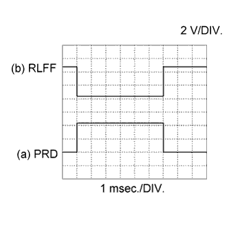 |
| Item |
Content |
| Terminal No. (Symbol) |
(a) C90-19 (PRD) - C93-1 (E1) (b) C92-4 (RLFF) - C93-1 (E1) |
| Tool Setting |
2 V/DIV., 1 msec./DIV. |
| Condition |
Engine warmed up, engine racing |
- HINT:
- The waveform becomes shorter as the engine speed.
| WAVEFORM 5 |
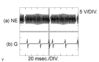 |
| Item |
Content |
| Terminal No. (Symbol) |
(a) C92-7 (NE+) - C92-8 (NE-) (b) C92-13 (G+) - C92-14 (G-) |
| Tool Setting |
5 V/DIV., 20 msec./DIV. |
| Condition |
Idling with warm engine |
- HINT:
- The waveform varies depending on the engine speed.
| WAVEFORM 6 |
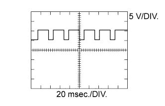 |
| Item |
Content |
| Terminal No. (Symbol) |
C93-15 (M+) - C93-1 (E1) |
| Tool Setting |
5 V/DIV., 20 msec./DIV. |
| Condition |
Idling with warm engine |
- HINT:
- The waveform varies depending on turbocharger operation.
| WAVEFORM 7 |
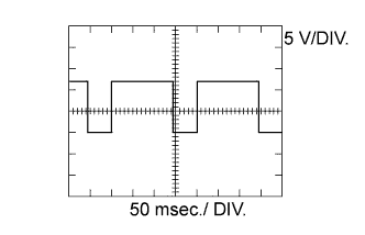 |
| Item |
Content |
| Terminal No. (Symbol) |
C93-14 (M-) - C93-1 (E1) |
| Tool Setting |
5 V/DIV., 50 msec./DIV. |
| Condition |
Idling with warm engine |
- HINT:
- The waveform varies depending on the turbocharger status.
| WAVEFORM 8 |
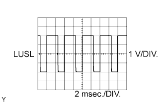 |
| Item |
Content |
| Terminal No. (Symbol) |
C92-15 (LUSL) - C93-1 (E1) |
| Tool Setting |
1 V/DIV., 2 msec./DIV. |
| Condition |
Racing with warm engine |
- HINT:
- The waveform varies depending on throttle valve operation.
| WAVEFORM 9 |
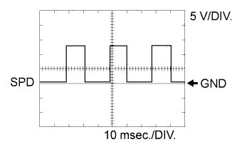 |
| Item |
Content |
| Terminal No. (Symbol) |
G58-30 (SPD) - C93-1 (E1) |
| Tool Setting |
5 V/DIV., 10 msec./DIV. |
| Condition |
Driving at vehicle speed of 40 km/h (25 mph) |
- HINT:
- The wavelength becomes shorter as the vehicle speed increases.
| WAVEFORM 10 |
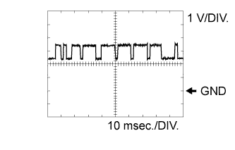 |
| Item |
Content |
| Terminal No. (Symbol) |
G58-36 (CANL) - C93-1 (E1) G57-21 (CANN) - C93-1 (E1) C92-18 (CAN-) - C93-1 (E1) |
| Tool Setting |
1 V/DIV., 10 msec./DIV. |
| Condition |
Engine stopped, engine switch on (IG) |
- HINT:
- The waveform varies depending on the CAN communication signal.
| WAVEFORM 11 |
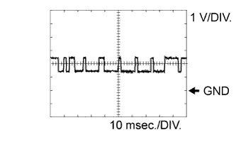 |
| Item |
Content |
| Terminal No. (Symbol) |
G58-35 (CANH) - C93-1 (E1) G57-20 (CANP) - C93-1 (E1) C92-24 (CAN+) - C93-1 (E1) |
| Tool Setting |
1 V/DIV., 10 msec./DIV. |
| Condition |
Engine stopped, engine switch on (IG) |
- HINT:
- The waveform varies depending on the CAN communication signal.