REASSEMBLY
Removal / installation · Vehicles built from Aug 2013
| 1. INSTALL BRAKE BOOSTER PISTON SUB-ASSEMBLY |

Apply a light coat of lithium soap base glycol grease to a new piston.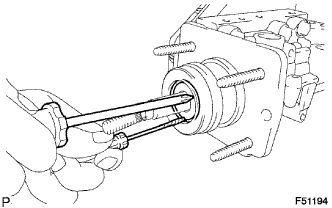

Install the piston.
- NOTICE:
- When installing, be careful not to damage the seals, etc.
Install the plug.
Using 2 screwdrivers, install a new C-ring while pressing in the piston.
- HINT:
- Tape the screwdriver tip before use.
| 2. INSTALL MASTER CYLINDER BOOT |
| 3. INSTALL MASTER CYLINDER PUSH ROD CLEVIS |
Install the brake master cylinder side lock nut and rod operating adapter to the brake master cylinder.
- Torque:
- 26 N*m{ 260 kgf*cm , 19 ft.*lbf }
Install the lock nut and master cylinder push rod clevis to the rod operating adapter.
- Torque:
- 26 N*m{ 260 kgf*cm , 19 ft.*lbf }
| 4. INSTALL MASTER CYLINDER SOLENOID |
Install a new gasket.
- NOTICE:
- Keep all surfaces of the master cylinder solenoid, master cylinder and gasket, especially contact surfaces, away from water and dust.
Install the master cylinder solenoid with 6 new bolts.
- Torque:
- 32 N*m{ 325 kgf*cm , 24 ft.*lbf }
| 5. INSTALL BRAKE BOOSTER ACCUMULATOR PIPE |
Install the brake booster accumulator pipe and compression spring.
- NOTICE:
- Make sure that no foreign matter enters the pump.
Install a new O-ring to the brake booster accumulator.
Install the brake booster accumulator.
- Torque:
- 57 N*m{ 585 kgf*cm , 42 ft.*lbf }
| 6. INSTALL NO. 3 BRAKE ACTUATOR BRACKET |
Install the No. 3 brake actuator bracket.
- Torque:
- 7.8 N*m{ 80 kgf*cm , 69 in.*lbf }
| 7. INSTALL NO. 1 BRAKE BOOSTER PUMP BRACKET |
Install the brake booster pump bush to the No. 1 brake booster pump bracket.
Using a 5 mm hexagon wrench, install the No. 1 brake booster pump bracket with the 2 bolts.
- Torque:
- 7.8 N*m{ 80 kgf*cm , 69 in.*lbf }
| 8. INSTALL BRAKE BOOSTER WITH ACCUMULATOR PUMP ASSEMBLY |
Using a 4 mm hexagon wrench, install the 2 pins to the brake master cylinder.
- Torque:
- 7.8 N*m{ 80 kgf*cm , 69 in.*lbf }
Install 2 new brake booster pump collars and 2 brake booster pump bushes to the brake booster with accumulator pump assembly.
Install the brake booster with accumulator pump assembly to the brake master cylinder.
Install a new clip.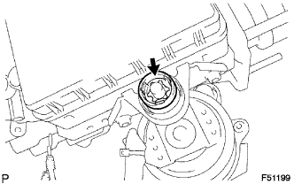
Connect the wire harnesses with the 2 screws.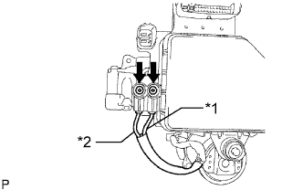
- Torque:
- 2.9 N*m{ 30 kgf*cm , 26 in.*lbf }
Text in Illustration *1
Red Cable
*2
Black Cable
Install 2 new plugs.
| 9. INSTALL NO. 1 BRAKE ACTUATOR TUBE |
Using a union nut wrench, install the No. 1 brake actuator tube.
- Torque:
- 15 N*m{ 155 kgf*cm , 11 ft.*lbf }
- NOTICE:
- Use the formula to calculate special torque values for situations where a union nut wrench is combined with a torque wrench (Click here).
| 10. INSTALL NO. 1 BRAKE ACTUATOR HOSE |
Using needle nose pliers, install the brake actuator hose with the 2 clips.
| 11. INSTALL MASTER CYLINDER RESERVOIR GROMMET |
Apply a light coat of lithium soap base glycol grease to 3 new reservoir grommets.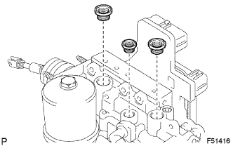
Install the 3 reservoir grommets to the brake master cylinder.
- NOTICE:
- Be careful of the size of each grommet.
| 12. INSTALL BRAKE MASTER CYLINDER RESERVOIR SUB-ASSEMBLY |
Install the brake master cylinder reservoir sub-assembly with the screw.
- Torque:
- 1.7 N*m{ 17 kgf*cm , 15 in.*lbf }
Install the master cylinder reservoir filler cap.
Using a pin punch and hammer, install a new pin to the brake master cylinder reservoir.
| 13. INSTALL NO. 1 BRAKE ACTUATOR BRACKET |
Install the brake fluid level warning switch connector to the No. 1 brake actuator bracket.
Using a 5 mm hexagon wrench, install the No. 1 brake actuator bracket with the bolt.
- Torque:
- 7.8 N*m{ 80 kgf*cm , 69 in.*lbf }