IG Power Source Circuit
Circuit diagnosis · Vehicles built from Aug 2014
Versions by build date: Aug 2013 – Jul 2014 from Aug 2014
DESCRIPTION
The main power source is supplied to the air conditioning amplifier assembly when the ignition switch is turned to ON. The power source is used for operating the air conditioning amplifier assembly, servo motors, etc.WIRING DIAGRAM
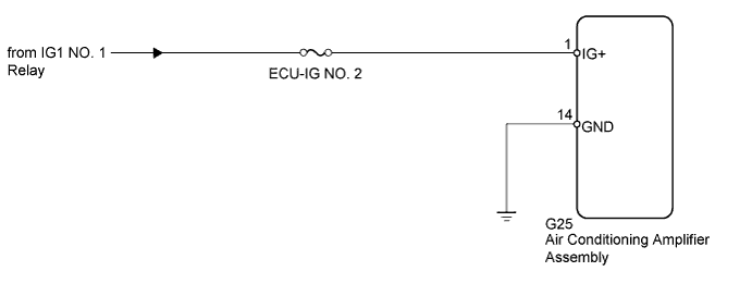

INSPECTION PROCEDURE
- NOTICE:
- Inspect the fuses for circuits related to this system before performing the following inspection procedure.
- HINT:
- Start the engine before inspection. Check the relays, fuses and battery if the engine does not start.
| 1. CHECK HARNESS AND CONNECTOR (AIR CONDITIONING AMPLIFIER - BATTERY AND BODY GROUND) |

Disconnect the G25 amplifier connector.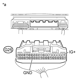
Measure the voltage according to the value(s) in the table below.
- Standard Voltage:
Tester Connection
Switch Condition
Specified Condition
G25-1 (IG+) - Body ground
Ignition switch off
Below 1 V
Ignition switch ON
11 to 14 V
Measure the resistance according to the value(s) in the table below.
- Standard Resistance:
Tester Connection
Condition
Specified Condition
G25-14 (GND) - Body ground
Always
Below 1 Ω
| *a |
Rear view of wire harness connector (to Air Conditioning Amplifier Assembly) |
|
|
||||

| OK | ||
 |
||
| ||