INSTALLATION
Removal / installation · Vehicles built Aug 2013 – Jul 2014
Versions by build date: Aug 2013 – Jul 2014 from Aug 2014
| 1. INSTALL SIDE TELEVISION CAMERA ASSEMBLY |

Install the side television camera with the 3 screws.
Connect the connector.
Attach the claw as shown in the illustration to install the part labeled A to the part labeled B.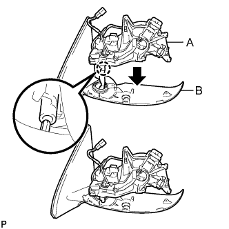

- NOTICE:
- Be careful not to break the claw.
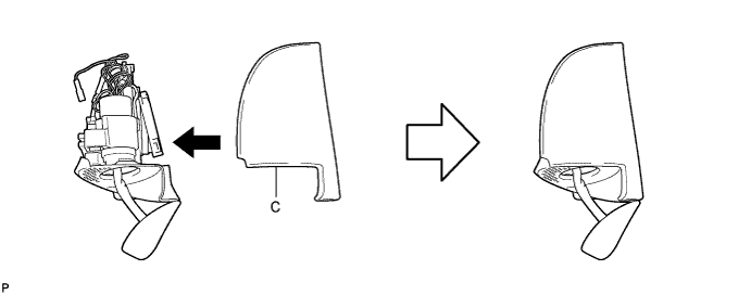
Attach the part labeled C as shown in the illustration.
Install the 5 screws.
Using a T25 "TORX" socket wrench, install the 3 screws.
- HINT:
- Clean the threads of the screw with non-residue solvent.
- Apply adhesive to the threads of the screw.
- Adhesive:
- Toyota Genuine Adhesive 1324, Three Bond 1324 or equivalent
- Clean the threads of the screw with non-residue solvent.
Attach the 8 claws to install the lower cover.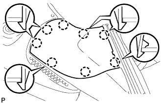
Attach the 4 claws to install the rubber base.
Install the screw.
Apply 2 new pieces of tape so that they overlap.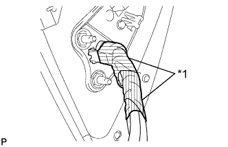
Text in Illustration *1
Tape
| 2. INSTALL SIDE TURN SIGNAL LIGHT ASSEMBLY LH |
Connect the connector.
Install the light with the 3 screws.
| 3. INSTALL OUTER MIRROR COVER |
Install the outer mirror cover.
Insert the rib on the outer edge of the cover into the groove of the mirror body.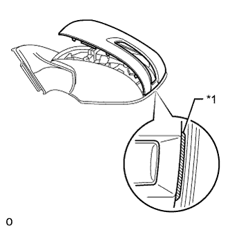
- NOTICE:
- Do not scratch the turn light.
Text in Illustration *1
Rib
Confirm that the cover and mirror body are aligned properly, and then push the outer end of the cover to attach the outer claws.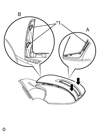
- NOTICE:
- Make sure that the upper ribs of the cover shown in part A of the illustration are properly attached to the mirror body.
- Make sure that the ribs of the mirror body shown in part B of the illustration are not protruding from the cover.
- Make sure that the upper ribs of the cover shown in part A of the illustration are properly attached to the mirror body.
Text in Illustration *1
Rib
While making sure that the rib of the cover fits properly into the groove of the mirror body, squeeze the inner end of the cover and the mirror body together to attach the inner claws.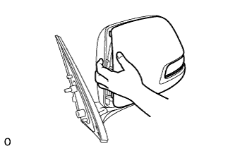
Push on the cover at the locations of the 8 claws to confirm that the claws are attached properly.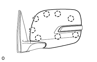
| 4. INSTALL OUTER REAR VIEW MIRROR GLASS |
Connect the connectors.
Attach the 4 claws to install the mirror glass.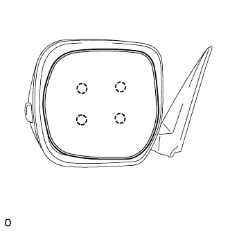
| 5. INSTALL OUTER REAR VIEW MIRROR ASSEMBLY LH |
Install the outer rear view mirror (Click here).
| 6. ADJUST SIDE TELEVISION CAMERA ASSEMBLY |
- HINT:
- Adjust the side television camera for the passenger side only.
Adjust the side television camera (Click here).