DISASSEMBLY
Removal / installation · Vehicles built from Aug 2013
| 1. INSPECT 5TH GEAR THRUST CLEARANCE |

Using a dial indicator, measure the thrust clearance.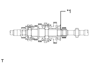

- Standard clearance:
- 0.10 to 0.30 mm (0.00394 to 0.0118 in.)
Text in Illustration *1
5th Gear
- If the result is not as specified, replace the 5th gear.
| 2. INSPECT 1ST GEAR THRUST CLEARANCE |
Using a dial indicator, measure the thrust clearance.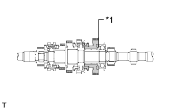
- Standard clearance:
- 0.10 to 0.25 mm (0.00394 to 0.00984 in.)
Text in Illustration *1
1st Gear
- If the result is not as specified, replace the No. 1 synchronizer ring set.
| 3. INSPECT 2ND GEAR THRUST CLEARANCE |
Using a dial indicator, measure the thrust clearance.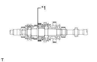
- Standard clearance:
- 0.10 to 0.25 mm (0.00394 to 0.00984 in.)
Text in Illustration *1
2nd Gear
- If the result is not as specified, replace the No. 1 synchronizer ring set.
| 4. INSPECT 3RD GEAR THRUST CLEARANCE |
Using a feeler gauge, measure the thrust clearance.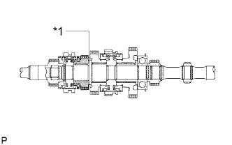
- Standard clearance:
- 0.10 to 0.25 mm (0.00394 to 0.00984 in.)
Text in Illustration *1
3rd Gear
- If the result is not as specified, replace the No. 2 synchronizer ring set.
| 5. INSPECT 1ST GEAR RADIAL CLEARANCE |
Using a dial indicator, measure the radial clearance.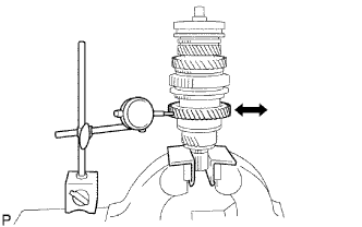
- Standard clearance:
- 0.009 to 0.056 mm (0.000355 to 0.00220 in.)
- If the result is not as specified, replace the 1st gear needle roller bearing.
| 6. INSPECT 2ND GEAR RADIAL CLEARANCE |
Using a dial indicator, measure the radial clearance.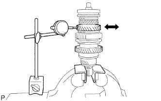
- Standard clearance:
- 0.008 to 0.034 mm (0.000315 to 0.00133 in.)
- If the result is not as specified, replace the 2nd gear needle roller bearing.
| 7. INSPECT 3RD GEAR RADIAL CLEARANCE |
Using a dial indicator, measure the radial clearance.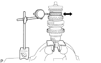
- Standard clearance:
- 0.008 to 0.034 mm (0.000315 to 0.00133 in.)
- If the result is not as specified, replace the 3rd gear needle roller bearing.
| 8. REMOVE 1ST GEAR |
Using 2 screwdrivers and a hammer, tap off the snap ring from the output shaft.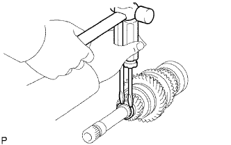
Using SST and a press, remove the 5th gear, center bearing, 1st gear bearing inner race, 1st gear and 1st gear needle roller bearing from the output shaft.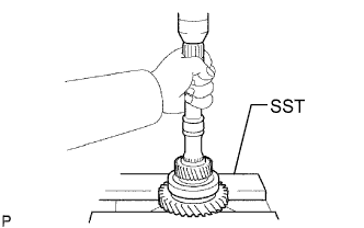
- SST
- 09527-10011
| 9. REMOVE NO. 1 SYNCHRONIZER RING (for 1st Gear) |
Remove the No. 1 synchronizer ring from the No. 1 clutch hub.
| 10. REMOVE 1ST GEAR BEARING INNER RACE LOCK BALL |
Using a magnet hand, remove the lock ball.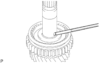
| 11. REMOVE 2ND GEAR |
Using SST and a press, remove the reverse gear, No. 1 transmission clutch hub, No. 1 synchronizer ring and 2nd gear.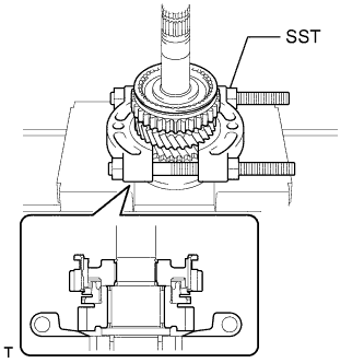
- SST
- 09950-00020
| 12. REMOVE NO. 2 SYNCHRONIZER RING (for 2nd Gear) |
Remove the No. 2 synchronizer ring from the 2nd gear.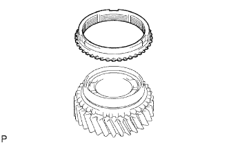
| 13. REMOVE 2ND GEAR NEEDLE ROLLER BEARING |
Remove the needle roller bearing from the output shaft.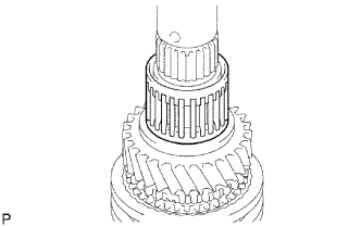
| 14. REMOVE NO. 1 TRANSMISSION CLUTCH HUB |
Remove the 2 synchromesh shifting key springs.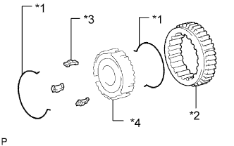
Remove the reverse gear and 3 synchromesh shifting keys from the transmission clutch hub.
Text in Illustration *1
No. 1 Synchromesh Shifting Key Spring
*2
Reverse Gear
*3
No. 1 Synchromesh Shifting Key
*4
No. 1 Transmission Clutch Hub
| 15. REMOVE 3RD GEAR |
Using a snap ring expander, remove the snap ring from the output shaft.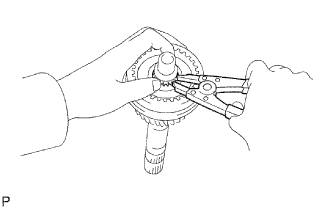
Using a press, remove the No. 2 transmission clutch hub and 3rd gear.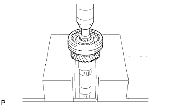
| 16. REMOVE NO. 1 SYNCHRONIZER RING |
Remove the No. 1 synchronizer ring from the 3rd gear.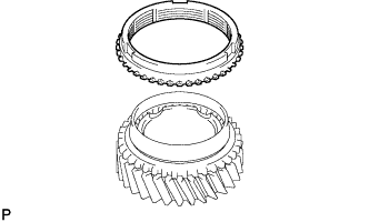
| 17. REMOVE 3RD GEAR NEEDLE ROLLER BEARING |
Remove the needle roller bearing from the output shaft.
| 18. REMOVE NO. 2 TRANSMISSION CLUTCH HUB |
Remove the 2 synchromesh shifting key springs.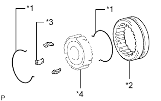
Remove the transmission hub sleeve and 3 synchromesh shifting keys from the transmission clutch hub.
Text in Illustration *1
No. 2 Synchromesh Shifting Key Spring
*2
No. 2 Transmission Hub Sleeve
*3
No. 2 Synchromesh Shifting Key
*4
No. 2 Transmission Clutch Hub