BM27T0E
_01
Vehicle Exterior
_054379
BODY DIMENSIONS
_0267638
FRAME(for 5 Door)
F
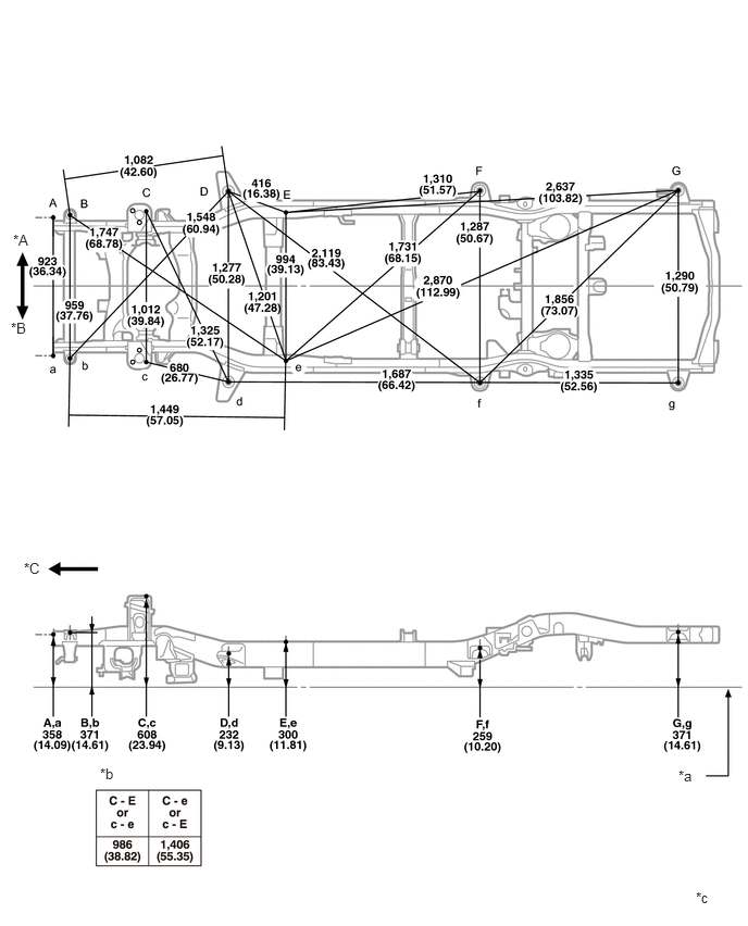
BODY DIMENSIONS FRAME(for 5 Door) THREE-DIMENSIONAL DISTANCE
Upper Face
- HINT:
-
For symbols, capital letters indicate right side of vehicle, small letters indicate left side of vehicle (seen from rear).
| Symbol | Name | Hole Diameter
mm (in.) |
|---|---|---|
| A, a | Front bumper reinforcement installation nut | M10 (0.39) |
| B, b | NO. 1 body mounting hole | φ26 (1.02) |
| C, c | Front spring support installation hole | φ12.15 (0.4783) |
| D, d | NO. 2 body mounting hole | φ43 (1.69) |
| E, e | Side rail inner channel standard hole | 16X16
(0.63X0.63) |
| F, f | NO. 3 body mounting hole | φ43 (1.69) |
| G, g | NO. 4 body mounting hole | φ43 (1.69) |
0.125,2.219 0.438,2.375
0.313,0.156
10
false
*A
0.104,3.063 0.417,3.219
0.313,0.156
10
false
*B
0.229,5.365 0.479,5.604
0.25,0.24
10
false
*C
6.5,7.354 6.813,7.656
0.313,0.302
10
false
*a
0.958,7.333 1.271,7.49
0.313,0.156
10
false
*b
6.667,8.521 6.979,8.677
0.313,0.156
10
false
*c
| *A | RH | *B | LH |
| *C | Front | - | - |
| *a | Imaginary Datum Line | *b | Vehicle Dimensions |
| *c | mm
(in.) |
- | - |
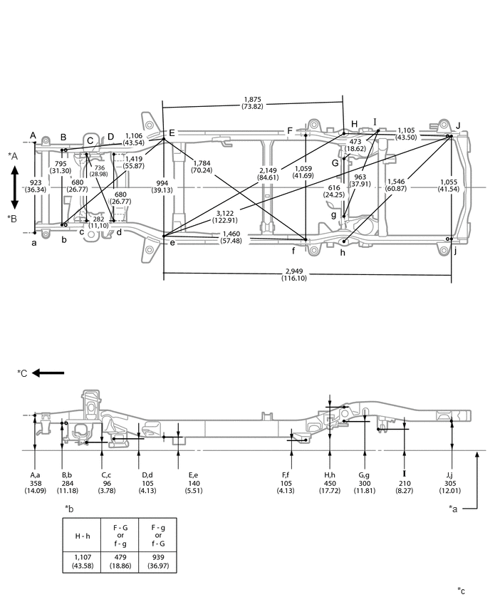
Lower Face
- HINT:
-
For symbols, capital letters indicate right side of vehicle, small letters indicate left side of vehicle (seen from rear).
| Symbol | Name | Hole Diameter
mm (in.) |
|---|---|---|
| A, a | Front bumper reinforcement installation nut | M10 (0.39) |
| B, b | Front stabilizer bracket installation nut | M10 (0.39) |
| C, c | Lower arm installation hole | 40X22
(1.57X0.87) |
| D, d | Lower arm installation hole | 34.5X16.5
(1.358X0.650) |
| E, e | Side rail inner channel standard hole | 16X16
(0.63X0.63) |
| F, f | Lower arm installation hole | φ14.2 (0.559) |
| G, g | Upper arm installation hole | φ12.2 (0.480) |
| H, h | Rear shock absorber installation hole | φ25 (0.98) |
| I | Lateral control rod installation hole | φ15 (0.59) |
| J, j | Transport hook installation nut | M12 (0.47) |
0.115,2.198 0.427,2.354
0.313,0.156
10
false
*A
0.104,3.115 0.417,3.271
0.313,0.156
10
false
*B
0.25,5.375 0.479,5.604
0.229,0.229
10
false
*C
6.563,7.354 6.781,7.552
0.219,0.198
10
false
*a
0.948,7.354 1.26,7.51
0.313,0.156
10
false
*b
6.688,8.552 7,8.708
0.313,0.156
10
false
*c
| *A | RH | *B | LH |
| *C | Front | - | - |
| *a | Imaginary Datum Line | *b | Vehicle Dimensions |
| *c | mm
(in.) |
- | - |
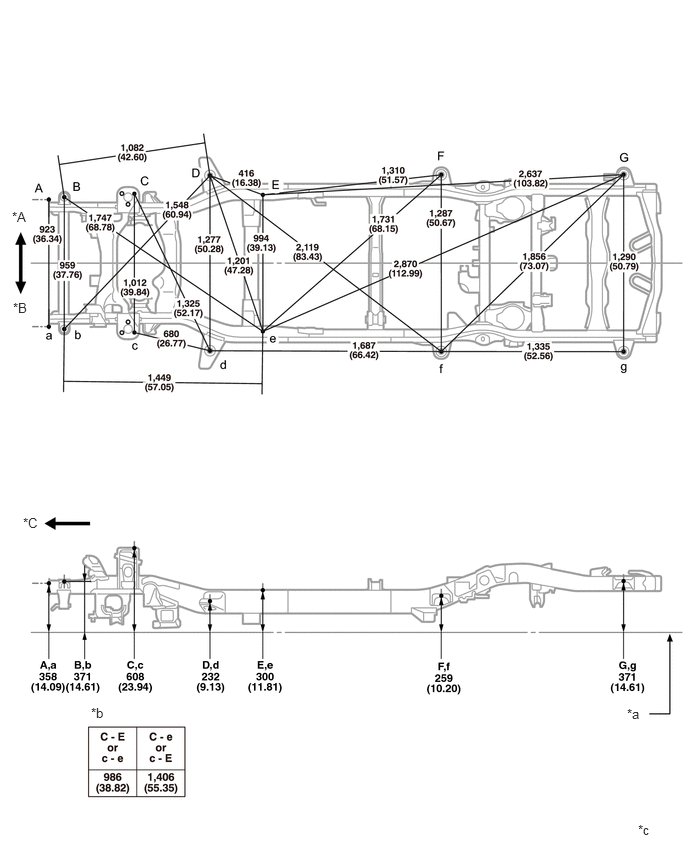
Upper Face (w/ Kinetic Dynamic Suspension System)
- HINT:
-
For symbols, capital letters indicate right side of vehicle, small letters indicate left side of vehicle (seen from rear).
| Symbol | Name | Hole Diameter
mm (in.) |
|---|---|---|
| A, a | Front bumper reinforcement installation nut | M10 (0.39) |
| B, b | No. 1 body mounting hole | φ26 (1.02) |
| C, c | Front spring support installation hole | φ12.15 (0.4783) |
| D, d | No. 2 body mounting hole | φ43 (1.69) |
| E, e | Side rail inner channel standard hole | 16X16
(0.63X0.63) |
| F, f | No. 3 body mounting hole | φ43 (1.69) |
| G, g | No. 4 body mounting hole | φ43 (1.69) |
0.125,2.177 0.385,2.385
0.26,0.208
10
false
*A
0.135,3.125 0.375,3.323
0.24,0.198
10
false
*B
0.24,5.365 0.448,5.594
0.208,0.229
10
false
*C
6.531,7.354 6.76,7.583
0.229,0.229
10
false
*a
0.948,7.344 1.26,7.5
0.313,0.156
10
false
*b
6.646,8.563 6.958,8.719
0.313,0.156
10
false
*c
| *A | RH | *B | LH |
| *C | Front | - | - |
| *a | Imaginary Datum Line | *b | Vehicle Dimensions |
| *c | mm
(in.) |
- | - |
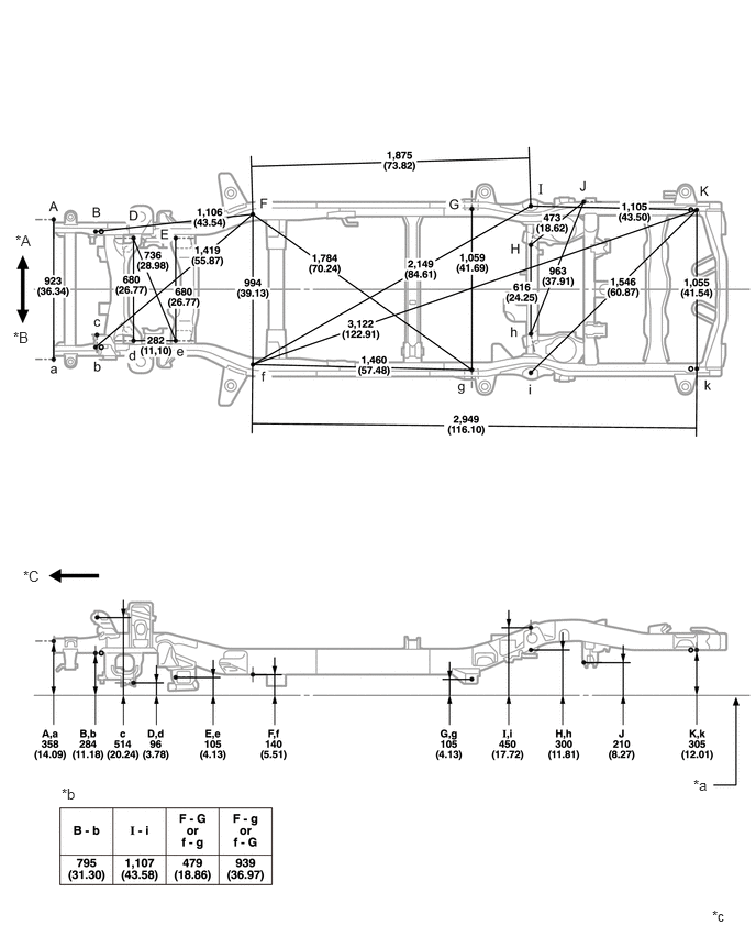
Lower Face (w/ Kinetic Dynamic Suspension System)
- HINT:
-
For symbols, capital letters indicate right side of vehicle, small letters indicate left side of vehicle (seen from rear).
| Symbol | Name | Hole Diameter
mm (in.) |
|---|---|---|
| A, a | Front bumper reinforcement installation nut | M10 (0.39) |
| B, b | Side rail inner channel hole | M10 (0.39) |
| c | Kinetic Dynamic Suspension System installation hole | φ15 (0.59) |
| D, d | Lower arm installation hole | 40X22
(1.57X0.87) |
| E, e | Lower arm installation hole | 34.5X16.5
(1.358X0.650) |
| F, f | Side rail inner channel standard hole | 16X16
(0.63X0.63) |
| G, g | Lower arm installation hole | φ14.2 (0.559) |
| H, h | Upper arm installation hole | φ12.2 (0.480) |
| I, i | Rear shock absorber installation hole | φ25 (0.98) |
| J | Lateral control rod installation hole | φ15 (0.59) |
| K, k | Transport hook installation nut | M12 (0.47) |
0.146,2.198 0.458,2.354
0.313,0.156
10
false
*A
0.125,3.115 0.438,3.271
0.313,0.156
10
false
*B
0.219,5.375 0.448,5.594
0.229,0.219
10
false
*C
6.573,7.354 6.792,7.604
0.219,0.25
10
false
*a
0.583,7.438 0.896,7.594
0.313,0.156
10
false
*b
6.75,8.594 7.063,8.75
0.313,0.156
10
false
*c
| *A | RH | *B | LH |
| *C | Front | - | - |
| *a | Imaginary Datum Line | *b | Vehicle Dimensions |
| *c | mm
(in.) |
- | - |