BODY PANEL FIT STANDARD / ADJUSTMENT METHOD ADJUSTMENT
Refer to the TOYOTA Repair Manual for adjustment method.
- HINT:
-
Vehicle Exterior > DOOR / HATCH
INSPECT HOOD SUB-ASSEMBLY
Check that the clearance measurements of areas A through F are within each standard range.
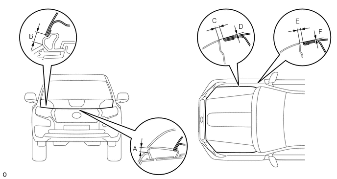
- Standard:
Area Measurement Area Measurement A 5.45 to 8.45 mm (0.215 to 0.333 in.) B 6.55 to 9.55 mm (0.258 to 0.376 in.) C 2.0 to 5.0 mm (0.079 to 0.197 in.) D -1.5 to 1.5 mm (-0.0591 to 0.0591 in.) E 2.0 to 5.0 mm (0.079 to 0.197 in.) F -1.5 to 1.5 mm (-0.0591 to 0.0591 in.)
- HINT:
- ·
Use the same procedure for RHD and LHD vehicles.
·The procedure listed below is for LHD vehicles.
·Centering bolts are used to mount the hood hinge and hood lock. The hood and hood lock cannot be adjusted with the centering bolts installed. Substitute the centering bolts with standard bolts when making adjustments.
·Centering bolts are used to mount the hood hinge and hood lock. The hood and hood lock cannot be adjusted with the centering bolts installed. Substitute the centering bolts with standard bolts when making adjustments.
INSPECT FRONT DOOR
for 5 Door:
Check that the clearance measurements of areas A through P are within the standard range.
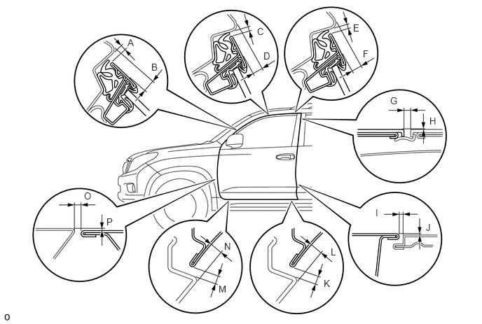
- Standard:
Area Measurement Area Measurement A 3.60 to 6.60 mm (0.142 to 0.260 in.) B 6.50 to 9.50 mm (0.256 to 0.374 in.) C 3.70 to 6.70 mm (0.146 to 0.264 in.) D 3.70 to 6.70 mm (0.146 to 0.264 in.) E 3.70 to 6.70 mm (0.146 to 0.264 in.) F 4.60 to 7.60 mm (0.181 to 0.299 in.) G 2.5 to 6.5 mm (0.0984 to 0.256 in.) H -2.0 to 2.0 mm (-0.0787 to 0.0787 in.) I 3.0 to 6.0 mm (0.118 to 0.236 in.) J -1.5 to 1.5 mm (-0.0591 to 0.0591 in.) K 4.05 to 7.05 mm (0.159 to 0.278 in.) L 4.45 to 7.45 mm (0.175 to 0.293 in.) M 4.05 to 7.05 mm (0.159 to 0.278 in.) N 4.35 to 7.35 mm (0.171 to 0.289 in.) O 2.7 to 5.7 mm (0.106 to 0.224 in.) P -1.5 to 1.5 mm (-0.0591 to 0.0591 in.)
for 3 Door:
Check that the clearance measurements of areas A through P are within the standard range.
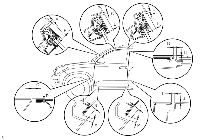
- Standard:
Area Measurement Area Measurement A 3.60 to 6.60 mm (0.142 to 0.260 in.) B 6.50 to 9.50 mm (0.256 to 0.374 in.) C 3.70 to 6.70 mm (0.146 to 0.264 in.) D 3.70 to 6.70 mm (0.146 to 0.264 in.) E 3.70 to 6.70 mm (0.146 to 0.264 in.) F 4.60 to 7.60 mm (0.181 to 0.299 in.) G 3.5 to 6.5 mm (0.138 to 0.256 in.) H -1.5 to 1.5 mm (-0.0591 to 0.0591 in.) I 2.7 to 5.7 mm (0.106 to 0.224 in.) J -1.5 to 1.5 mm (-0.0591 to 0.0591 in.) K 4.05 to 7.05 mm (0.159 to 0.278 in.) L 4.45 to 7.45 mm (0.175 to 0.293 in.) M 4.05 to 7.05 mm (0.159 to 0.278 in.) N 4.35 to 7.35 mm (0.171 to 0.289 in.) O 2.7 to 5.7 mm (0.106 to 0.224 in.) P -1.5 to 1.5 mm (-0.0591 to 0.0591 in.)
- HINT:
- ·
Use the same procedure for the RH and LH sides.
·The procedure listed below is for the LH side.
·Centering bolts are used to mount the door hinge to the vehicle body and door. The door cannot be adjusted with the centering bolts installed on it. Substitute the centering bolts with standard bolts when making adjustments.
INSPECT REAR DOOR
Check that the clearance measurements of areas A through N are within the standard range.
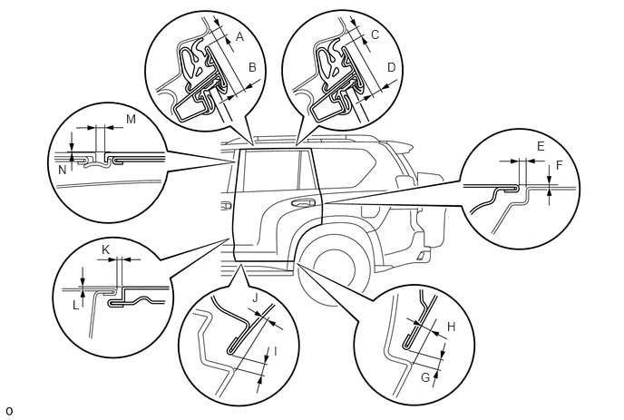
- Standard:
Area Measurement Area Measurement A 3.7 to 6.7 mm (0.146 to 0.264 in.) B 4.2 to 7.2 mm (0.165 to 0.284 in.) C 3.6 to 6.6 mm (0.142 to 0.260 in.) D 4.9 to 7.9 mm (0.193 to 0.311 in.) E 2.7 to 5.7 mm (0.106 to 0.224 in.) F -1.5 to 1.5 mm (-0.0591 to 0.0591 in.) G 4.05 to 7.05 mm (0.159 to 0.278 in.) H 4.45 to 7.45 mm (0.1752 to 0.2933 in.) I 4.05 to 7.05 mm (0.159 to 0.278 in.) J 4.45 to 7.45 mm (0.1752 to 0.2933 in.) K 3.0 to 6.0 mm (0.118 to 0.236 in.) L -1.5 to 1.5 mm (-0.0591 to 0.0591 in.) M 2.5 to 6.5 mm (0.0984 to 0.256 in.) N -2.0 to 2.0 mm (-0.0787 to 0.0787 in.)
- HINT:
- ·
Use the same procedure for the RH and LH sides.
·The procedure listed below is for the LH side.
·Centering bolts are used to mount the door hinge to the vehicle body and door. The door cannot be adjusted with the centering bolts installed. Substitute the centering bolts with standard bolts when making adjustments.
INSPECT BACK DOOR
w/ Back Door Tire Carrier:
Check that the clearance measurements of areas A through I are within the standard range.
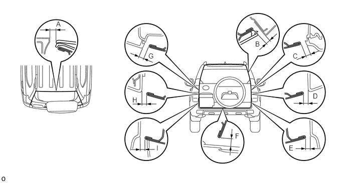
- Standard:
Area Measurement Area Measurement A 8.35 to 11.35 mm (0.329 to 0.447 in.) B 4.65 to 7.65 mm (0.183 to 0.301 in.) C 5.05 to 8.05 mm (0.199 to 0.317 in.) D 5.25 to 8.25 mm (0.207 to 0.325 in.) E 5.25 to 8.25 mm (0.207 to 0.325 in.) F 8.85 to 11.85 mm (0.348 to 0.467 in.) G 4.85 to 7.85 mm (0.191 to 0.309 in.) H 5.25 to 8.25 mm (0.207 to 0.325 in.) I 5.25 to 8.25 mm (0.207 to 0.325 in.) - -
w/o Back Door Tire Carrier:
Check that the clearance measurements of areas A through I are within the standard range.
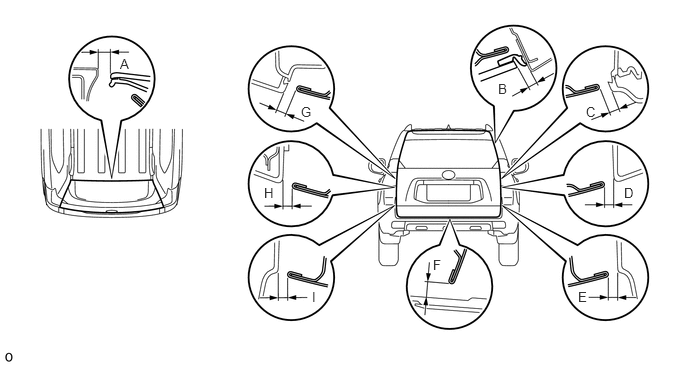
- Standard:
Area Measurement Area Measurement A 8.35 to 11.35 mm (0.329 to 0.447 in.) B 5.05 to 8.05 mm (0.199 to 0.317 in.) C 4.65 to 7.65 mm (0.183 to 0.301 in.) D 4.95 to 7.95 mm (0.195 to 0.313 in.) E 4.95 to 7.95 mm (0.195 to 0.313 in.) F 8.85 to 11.85 mm (0.348 to 0.467 in.) G 4.65 to 7.65 mm (0.183 to 0.301 in.) H 4.95 to 7.95 mm (0.195 to 0.313 in.) I 5.05 to 8.05 mm (0.199 to 0.317 in.) - -
- HINT:
-
Centering bolts are used to mount the door hinge to the vehicle body and door. The door cannot be adjusted with the centering bolts installed. Substitute the centering bolts with standard bolts (with washers) when making adjustments.