Home › Engine / Hybrid System › 2TR-FE FUEL › FUEL SYSTEM
NM27T0E _51 Engine / Hybrid System _053581 2TR-FE FUEL _0260106 FUEL SYSTEM UN GENERAL/CONTROL/DETAILS F

2TR-FE FUEL  FUEL SYSTEM  GENERAL/CONTROL/DETAILS  DETAILS  


CONSTRUCTION


a.

Fuel Injector Assembly

i.

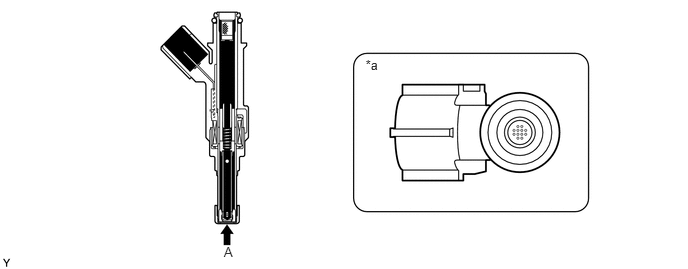
12-hole type fuel injector assembly is provided.


ii.

The fuel injector assembly is shaped to form a long nozzle. This shortens the distance from the fuel injector assembly to the intake valve, which prevents the fuel from adhering to the intake port walls and reduces HC exhaust emissions.
W126196E01
3.808,0.592 3.964,0.773 0.156,0.181 10 *a 2.332,2.546 2.488,2.728 0.156,0.181 10 A

Text in Illustration
*a View from A - -


b.

Fuel Delivery Pipe Sub-assembly

i.

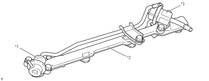
Steel plating is used for the fuel delivery pipe in order to enlarge the fuel capacity and reduce fuel pulsation.


ii.

The fuel pulsation is reduced via a pulsation damper in order to help stabilize the air-fuel ratio and reduce noise.


iii.

The fuel pressure in the fuel delivery pipe is adjusted according to the atmospheric pressure via the fuel pressure regulator.
W127699E04
0.677,1.656 1.323,2.031 true 3.708,1.635 4.323,1.948 true 5.708,0.427 6.188,0.188 true 0.51,1.531 0.688,1.76 0.177,0.229 10 false *1 4.354,1.906 4.594,2.135 0.24,0.229 10 false *2 6.198,0.052 6.417,0.302 0.219,0.25 10 false *3

Text in Illustration
*1 Pressure Regulator *2 Fuel Delivery Pipe Sub-assembly
*3 Pulsation Damper - -


c.

Fuel Tank

i.

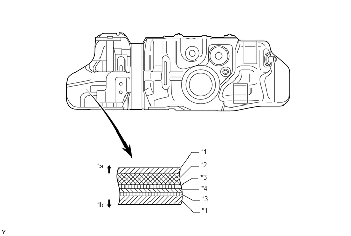
A multiplex layered plastic fuel tank is used for the fuel tank on the 5-door models with single fuel tank, and for the main fuel tank on the models with dual fuel tank.


ii.

A steel fuel tank is used for the fuel tank on 3-door models with single fuel tank, and for the sub fuel tank on 5-door models with dual fuel tank.


iii.

The multiplex layered plastic fuel tank consists of six layers of four types of materials, and one of those is a recyclable material to address environmental concerns.
W100649E05
3.688,3.875 4.063,3.875 true 3.656,3.469 3.917,3.115 3.917,3.115 4.063,3.115 true 3.635,3.667 3.906,3.396 3.906,3.396 4.063,3.396 true 3.688,3.958 3.938,4.094 3.938,4.094 4.083,4.094 true 3.688,4.083 3.948,4.333 3.948,4.333 4.094,4.333 true 4.052,3.646 3.927,3.646 3.927,3.646 3.667,3.802 true 1.979,3.302 2.188,3.531 0.208,0.229 10 false *a 1.979,4.104 2.188,4.333 0.208,0.229 10 false *b 4.094,3.021 4.313,3.219 0.219,0.198 10 false *1 4.094,3.281 4.302,3.51 0.208,0.229 10 false *2 4.094,3.542 4.302,3.771 0.208,0.229 10 false *3 4.104,3.76 4.313,3.99 0.208,0.229 10 false *4 4.115,3.979 4.323,4.208 0.208,0.229 10 false *3 4.115,4.219 4.354,4.469 0.24,0.25 10 false *1

Text in Illustration
*1 High Density Polyethylene (HDPE) *2 Regrind Material
*3 Adhesive *4 Ethylene Vinyl Alcohol Copolymer (EVOH)
*a Fuel Tank Outside *b Fuel Tank Inside


iv.

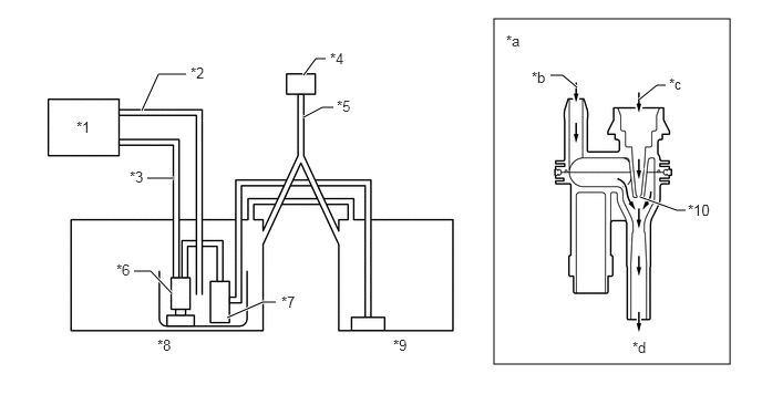
On the models with dual fuel tank, a jet pump is provided in the fuel tank in order to automatically transfer fuel from the fuel sub tank to the fuel tank.

·

The fuel from the fuel pump passes through the orifice in the jet pump and returns to the fuel tank. Because the flow speed of the fuel from the fuel pump increases as it passes through the orifice, a vacuum is created near the exit of the orifice. This vacuum causes the fuel to be drawn from the fuel sub tank to the fuel tank.
W102393E03
4.646,0.177 6.865,3.427 2.219,3.25 1.333,1.042 1.49,0.698 1.49,0.698 1.75,0.698 true 1.635,1.677 1.385,1.677 true 1.615,2.76 1.417,2.552 1.417,2.552 1.26,2.552 true 2.135,2.99 2.469,2.844 2.469,2.844 2.594,2.844 true 2.854,1.104 3.031,1.01 3.031,1.01 3.135,1.01 true 2.854,0.708 2.969,0.552 2.969,0.552 3.063,0.552 true 5.427,0.823 5.292,0.708 5.292,0.708 5.177,0.708 true 6.01,0.938 6.177,0.802 6.177,0.802 6.26,0.802 true 6.021,1.854 6.365,1.979 6.365,1.979 6.448,1.979 true 0.719,1.115 0.979,1.313 0.26,0.198 10 false *1 1.792,0.604 2.146,0.854 0.354,0.25 10 false *2 1.219,1.583 1.573,1.833 0.354,0.25 10 false *3 3.104,0.469 3.458,0.719 0.354,0.25 10 false *4 3.167,0.917 3.521,1.167 0.354,0.25 10 false *5 2.646,2.76 3,3.01 0.354,0.25 10 false *7 1.094,2.458 1.448,2.708 0.354,0.25 10 false *6 1.479,3.167 1.833,3.417 0.354,0.25 10 false *8 3.698,3.167 4.052,3.417 0.354,0.25 10 false *9 5,0.646 5.354,0.896 0.354,0.25 10 false *b 6.292,0.708 6.646,0.958 0.354,0.25 10 false *c 6.469,1.896 6.823,2.146 0.354,0.25 10 false *10 5.948,3.188 6.302,3.438 0.354,0.25 10 false *d 4.76,0.302 5.031,0.542 0.271,0.24 10 false *a

Text in Illustration
*1 Engine *2 Return Tube
*3 Main Tube *4 Fuel Inlet
*5 Fuel Filler Pipe *6 Fuel Pump
*7 Jet Pump *8 Main Fuel Tank
*9 Sub Fuel Tank *10 Orifice
*a Jet Pump Cross Section *b From Fuel Sub Tank
*c From Fuel Pump *d To Fuel Tank


OPERATION


a.

Sub Fuel Tank System

i.

The fuel from the fuel pump actuates the jet pump in the fuel tank, in order to draw fuel from the sub fuel tank to the main fuel tank.
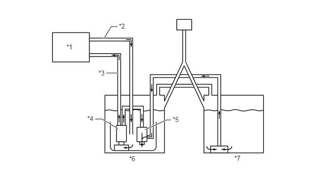
W102394E03
2.229,0.833 2.385,0.573 2.385,0.573 2.521,0.573 true 2.542,1.573 2.281,1.573 true 2.531,2.771 2.188,2.563 2.188,2.563 2.042,2.563 true 3.115,2.792 3.573,2.583 3.573,2.583 3.667,2.583 true 1.427,0.927 1.781,1.208 0.354,0.281 10 false *1 2.552,0.479 2.906,0.76 0.354,0.281 10 false *2 2.115,1.49 2.469,1.771 0.354,0.281 10 false *3 1.875,2.469 2.229,2.75 0.354,0.281 10 false *4 2.771,3.333 3.125,3.615 0.354,0.281 10 false *6 5.031,3.323 5.385,3.604 0.354,0.281 10 false *7 3.708,2.49 4.063,2.771 0.354,0.281 10 false *5

Text in Illustration
*1 Engine *2 Return Tube
*3 Main Tube *4 Fuel Pump
*5 Jet Pump *6 Main Fuel Tank
*7 Sub Fuel Tank - -