Home › Drivetrain › R150F MANUAL TRANSMISSION / TRANSAXLE › MANUAL TRANSMISSION SYSTEM
NM27T0E _52 Drivetrain _053616 R150F MANUAL TRANSMISSION / TRANSAXLE _0260147 MANUAL TRANSMISSION SYSTEM UN GENERAL/CONTROL/DETAILS F

R150F MANUAL TRANSMISSION / TRANSAXLE  MANUAL TRANSMISSION SYSTEM  GENERAL/CONTROL/DETAILS  DETAILS  


CONSTRUCTION


a.

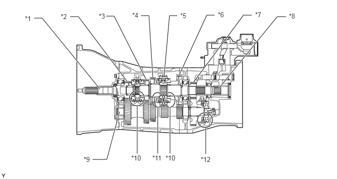
Gear Train

i.

The transmission synchromesh mechanism is an all-speed constant mesh type.
U170787E03
1.969,3.396 2.271,3.396 2.271,3.396 2.542,2.375 true 1.49,0.354 1.667,0.354 1.667,0.354 2.708,1.74 true 0.729,0.385 0.896,0.385 0.896,0.385 2.125,1.896 true 2.26,0.344 2.427,0.344 2.427,0.344 3.115,1.708 true 3,0.333 3.167,0.333 3.167,0.333 3.25,1.646 true 3.771,0.333 3.604,0.333 3.604,0.333 3.49,1.604 true 4.563,0.323 4.396,0.323 4.396,0.323 3.813,1.594 true 5.354,0.323 5.177,0.323 5.177,0.323 4.115,1.75 true 6.083,0.354 5.896,0.354 5.896,0.354 4.615,1.927 true 2.917,2.25 2.917,3.271 true 3.354,2.281 3.354,3.271 true 3.615,2.281 3.615,3.271 true 4.375,2.719 4.375,3.281 true 0.531,0.313 0.802,0.635 0.271,0.323 10 false *1 1.292,0.271 1.563,0.594 0.271,0.323 10 false *2 2.104,0.26 2.375,0.583 0.271,0.323 10 false *3 2.813,0.24 3.083,0.563 0.271,0.323 10 false *4 3.833,0.25 4.104,0.573 0.271,0.323 10 false *5 4.635,0.229 4.906,0.552 0.271,0.323 10 false *6 5.427,0.229 5.698,0.552 0.271,0.323 10 false *7 1.781,3.313 2.052,3.635 0.271,0.323 10 false *9 2.792,3.281 3.063,3.604 0.271,0.323 10 false *10 3.24,3.281 3.51,3.604 0.271,0.323 10 false *11 4.271,3.313 4.542,3.635 0.271,0.323 10 false *12 6.146,0.26 6.417,0.583 0.271,0.323 10 false *8 3.521,3.281 3.792,3.604 0.271,0.323 10 false *10

Text in Illustration
*1 Input Shaft *2 4th Gear
*3 3rd Gear *4 2nd Gear
*5 Reverse Gear *6 1st Gear
*7 5th Gear *8 Output Shaft
*9 Counter Shaft *10 Single-cone Type Synchromesh Mechanism
*11 Triple-cone Type Synchromesh Mechanism *12 Reverse Synchromesh Mechanism

Synchromesh Mechanism
Gear 1st 2nd 3rd, 4th and 5th Reverse
Synchromesh Mechanism Type Single-cone Triple-cone Single-cone Reverse


b.

Reverse Synchromesh Mechanism

i.

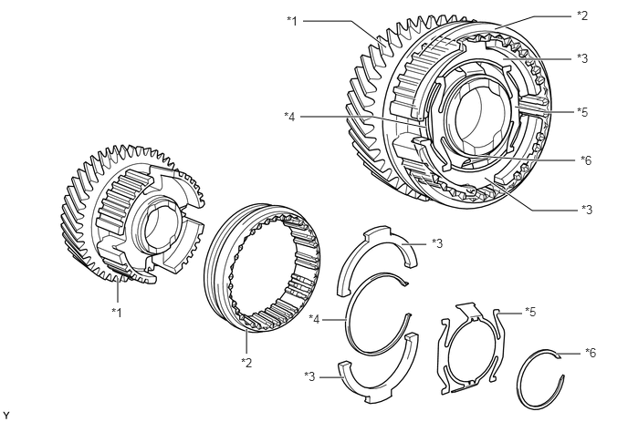
The reverse synchromesh mechanism consists of 2 shifting keys, a shifting key spring, and a shifting key return spring.
X102222E03
4.583,2.792 4.865,2.792 true 5.677,3.583 5.958,3.583 true 6.344,4.042 6.625,4.042 true 3.677,3.656 3.958,3.656 true 3.646,4.313 3.927,4.313 true 2.813,4.042 2.813,3.76 true 1.344,3.458 1.344,3.177 true 4.406,0.542 4.01,0.24 4.01,0.24 3.458,0.24 true 4.865,1.458 4.25,1.333 4.25,1.333 3.427,1.333 true 5.646,0.333 6.094,0.188 6.094,0.188 6.521,0.188 true 5.875,1.219 6.219,1.281 6.219,1.281 6.552,1.281 true 5.448,1.781 6.135,1.833 6.135,1.833 6.563,1.833 true 5.531,2.031 6.073,2.406 6.073,2.406 6.594,2.406 true 5.74,0.677 6.521,0.677 true 2.75,4.063 3.021,4.396 0.271,0.333 10 false *2 3.469,4.219 3.74,4.552 0.271,0.333 10 false *3 4.927,2.698 5.198,3.031 0.271,0.333 10 false *3 3.521,3.563 3.792,3.896 0.271,0.333 10 false *4 3.271,0.156 3.542,0.49 0.271,0.333 10 false *1 3.24,1.25 3.51,1.583 0.271,0.333 10 false *4 6.583,0.094 6.854,0.427 0.271,0.333 10 false *2 5.99,3.479 6.26,3.813 0.271,0.333 10 false *5 6.677,3.948 6.948,4.281 0.271,0.333 10 false *6 1.271,3.49 1.542,3.823 0.271,0.333 10 false *1 6.583,0.583 6.854,0.917 0.271,0.333 10 false *3 6.583,1.198 6.854,1.531 0.271,0.333 10 false *5 6.625,1.75 6.896,2.083 0.271,0.333 10 false *6 6.635,2.313 6.906,2.646 0.271,0.333 10 false *3

Text in Illustration
*1 Counter 5th Gear *2 Hub Sleeve
*3 Shifting Key *4 Shifting Key Spring
*5 Shifting Key Return Spring *6 Snap Ring


OPERATION


a.

Reverse Synchromesh Mechanism

i.

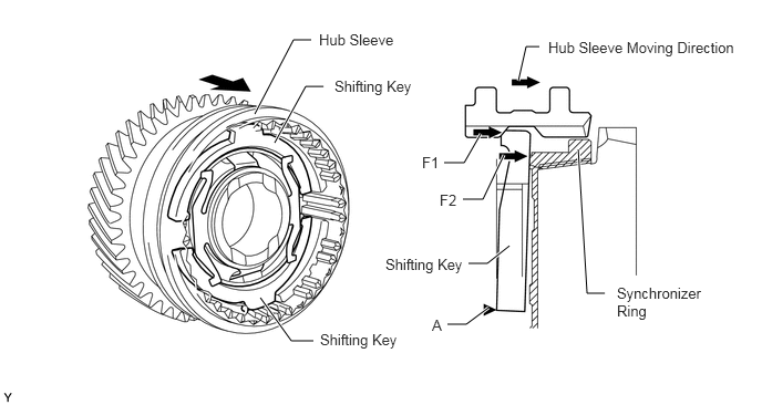
While shifting into 5th, the 2 shifting keys move in unison with the hub sleeve (F1). With "A" acting as the fulcrum, the 2 shifting keys move to push the synchronizer ring only for the amount of the lever ratio (F2). The shift effort can be reduced only by this amount.
X102223E03
4.875,0.76 4.948,0.438 4.948,0.438 5.073,0.438 true 2.396,1.073 2.76,0.375 2.76,0.375 2.927,0.375 true 2.583,1.344 2.875,0.813 2.875,0.813 3.042,0.813 true 2.448,2.802 2.74,3.208 2.74,3.208 2.948,3.208 true 5.438,1.406 5.521,2.76 5.521,2.76 5.688,2.76 true 4.792,2.313 4.583,2.479 4.583,2.479 4.406,2.479 true 4.594,2.896 4.385,3.052 4.385,3.052 4.208,3.052 true 4.74,1.458 4.542,1.875 4.542,1.875 4.354,1.875 true 4.521,1.26 4.365,1.531 4.365,1.531 4.177,1.531 true 3,0.292 3.771,0.646 0.771,0.354 10 false Hub Sleeve 5.156,0.365 7.073,0.719 1.917,0.354 10 false Hub Sleeve Moving Direction 3.146,0.729 3.917,1.083 0.771,0.354 10 false Shifting Key 3.625,2.406 4.396,2.76 0.771,0.354 10 false Shifting Key 3.969,1.448 4.198,1.802 0.229,0.354 10 false F1 4.135,1.802 4.365,2.156 0.229,0.354 10 false F2 4.063,2.979 4.26,3.333 0.198,0.354 10 false A 3.01,3.115 3.781,3.469 0.771,0.354 10 false Shifting Key 5.802,2.677 6.708,3.396 0.906,0.719 10 false Synchronizer Ring


ii.

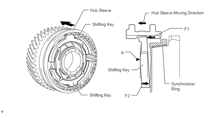
While shifting into reverse, with "B" acting as the fulcrum, the 2 shifting keys move to push the synchronizer ring (F2). As a result, a brake is applied to the rotation of the counter shaft and gear noise is prevented.
X102224E03
4.802,0.76 4.875,0.438 4.875,0.438 4.99,0.438 true 2.438,1.031 2.802,0.333 2.802,0.333 2.969,0.333 true 2.573,1.344 2.865,0.813 2.865,0.813 3.031,0.813 true 2.438,2.771 2.729,3.177 2.729,3.177 2.938,3.177 true 5.438,1.438 5.521,2.792 5.521,2.792 5.688,2.792 true 4.792,2.167 4.583,2.333 4.583,2.333 4.406,2.333 true 4.573,1.969 4.365,1.74 4.365,1.74 4.188,1.74 true 4.781,2.792 4.583,3.188 4.583,3.188 4.396,3.188 true 5.104,1.24 5.698,0.948 5.698,0.948 6.125,0.948 true 3.021,0.26 3.792,0.615 0.771,0.354 10 false Hub Sleeve 5.073,0.344 6.99,0.698 1.917,0.354 10 false Hub Sleeve Moving Direction 3.094,0.729 3.865,1.083 0.771,0.354 10 false Shifting Key 3.615,2.25 4.385,2.604 0.771,0.354 10 false Shifting Key 6.177,0.885 6.406,1.24 0.229,0.354 10 false F1 4.188,3.115 4.417,3.469 0.229,0.354 10 false F2 4.052,1.677 4.25,2.031 0.198,0.354 10 false A 3,3.094 3.771,3.448 0.771,0.354 10 false Shifting Key 5.74,2.719 6.625,3.427 0.885,0.708 10 false Synchronizer Ring