HEATING / AIR CONDITIONING AIR CONDITIONING SYSTEM GENERAL/CONTROL/DETAILS GENERAL
OUTLINE
Air Condition System
4 models are provided: manual and automatic single air conditioning models, and manual and automatic dual air conditioning models equipped with a rear air conditioning unit.
The automatic air conditioning system uses left and right independent temperature control to enhance comfort.
Combustion Type Power Heater (Models with Combustion Type Power Heater)
Depending on the operating condition, the engine coolant temperature remains low, making it difficult to ensure the proper heating effect. Thus, in order to provide an adequate heating effect, a combustion type power heater is provided.
A heater switch assembly (power heater switch) is located in the driver side of the instrument panel.
SPECIFICATION
Single Air Conditioning Model
Performance
| Heater | Heater Output | 5750 W |
| Air Flow Volume | 350 m3/h | |
| Power Consumption | 250 W | |
| Quick Heater Assembly*1 | Heat Output | 840 W |
| Cooler | Cooling Capacity | 5470*2 or 5900*3 |
| Air Flow Volume | 540 m3/h | |
| Power Consumption | 300 W |
*1: Models with quick heater assembly
*2: Except models for G.C.C. countries
*3: Models for G.C.C. countries
Ventilation and Heater Core
| Heater Radiator Unit Sub-assembly | Type | Straight Flow Aluminum-II (SFA-II) |
| Size W x H x L | 243.2 mm x 140 mm x 27 mm (9.6 in. x 5.5 in. x 1.1 in.) | |
| Fin Pitch | 1.5 mm (0.06 in.) | |
| Blower with Fan Motor Assembly | Motor Type | K70-BMM 11T |
| Fan Type | Semi Sirocco | |
| Fan Size (Dia. x H) | 165 mm x 70 mm (6.5 in. x 2.8 in.) |
Air Conditioning
| Cooler Condenser Assembly | Type | Multi-flow-IV (MF-IV) Sub-cool |
| Size W x H x L | 600 mm x 491.8 mm x 16 mm (23.6 in. x 19.4 in. x 0.6 in.)*1
600 mm x 511 mm x 16 mm (23.6 in. x 20.1 in. x 0.6 in.)*2 |
|
| Fin Pitch | 3.15 mm (0.12 in.) | |
| Cooler Compressor Assembly | Motor Type | 10S17C*3
10SRE18C*4 |
| Refrigerant | Type | HFC-134a (R134a)*5
HFO-1234yf (R1234yf)*6 |
| Charge Volume | 550*7, *8
600*9, *10 |
|
| Evaporator | Type | Revolutionary Super-slim (RS) Structure |
| Size W x H x L | 252.9 mm x 231 mm x 38 mm (10.0 in. x 9.1 in. x 1.5 in.)*5
252.9 mm x 235 mm x 50 mm (10.0 in. x 9.3 in. x 2.0 in.)*8 |
|
| Fin Pitch | 2.6 mm (0.1 in.)*5, 3.0 mm (0.12 in.)*9 |
*1: Models with 1GR-FE engine
*2: Except models with 1GR-FE engine
*3: Except models with 1GD-FTV engine or 2TR-FE engine
*4: Models with 1GD-FTV engine or 2TR-FE engine
*5: Models using HFC-134a (R134a) refrigerant
*6: Models using HFO-1234yf (R1234yf) refrigerant
*7: Except models for G.C.C. countries
*8: Models without cool box
*9: Models with cool box
*10: Models for G.C.C. countries
Dual Air Conditioning Model
Performance
| Model | Front | Rear | |
|---|---|---|---|
| Heater | Heater Output | 5750 W | 2500 W |
| Air Flow Volume | 350 m3h | 140 m3h | |
| Power Consumption | 250 W | 125 W | |
| Quick Heater Assembly*1 | Heat Output | 840W | - |
| Cooler | Cooling Capacity | 5470 W*2 or 5900 W*3 | 3600 W |
| Air Flow Volume | 540 m3/h | 320 m3/h | |
| Power Consumption | 300 W | 200 W | |
*1: Models with quick heater assembly
*2: Except models for G.C.C. countries
*3: Models for G.C.C. countries
Ventilation and Heater Core
| Model | Front | Rear | |
|---|---|---|---|
| Heater Radiator Unit Sub-assembly | Type | Straight Flow Aluminum-II (SFA-II) | Straight Flow Aluminum-II (SFA-II) |
| Size W x H x L | 243.2 mm x 140 mm x 27 mm (9.7 in. x 5.6 in. x 1.1 in.) | 191.1 mm x 130 mm x 21 mm (7.5 in. x 5.1 in. x 0.8 in.) | |
| Fin Pitch | 1.5 mm (0.06 in.) | 1.8 mm (0.13 in.) | |
| Blower with Fan Motor Assembly | Motor Type | K70-BMM 11T | K62 |
| Fan Type | Semi Sirocco | High Level of Pressure Loss | |
| Fan Size (Dia. x H) | 165 mm x 70 mm (6.5 in. x 2.8 in.) | 140 mm x 65 mm (5.5 in. x 2.6 in.) | |
Air Conditioning
| Model | Front | Rear | |
|---|---|---|---|
| Cooler Condenser Assembly | Type | Multi-flow-IV (MF-IV) Sub-cool | |
| Size W x H x L | 600 mm x 491.8 mm x 16 mm (23.6 in. x 19.7 in. x 0.6 in.)*1
600 mm x 511 mm x 16 mm (23.6 in. x 20.4 in. x 0.6 in.)*2 |
||
| Fin Pitch | 3.15 mm (0.13 in.) | ||
| Cooler Compressor Assembly | Motor Type | 10S17C*3
10SRE18C*4 |
|
| Refrigerant | Type | HFC-134a (R134a)*5
HFO-1234yf (R1234yf)*6 |
|
| Charge Volume | 720*7, 770*8, *9, 800*10 | ||
| Evaporator | Type | Revolutionary Super-slim (RS) Structure | |
| Size W x H x L | 252.9 mm x 231mm x 38 mm (10.0 in. x 9.1 in. x 1.5 in.)*11
252.9 mm x 235 mm x 50 mm (10.0 in. x 9.3 in. x 2.0 in.)*12 |
145.7 mm x 255 mm x 50 mm
(5.7 in. x 10.0 in. x 2.0 in.) |
|
| Fin Pitch | 2.6 mm (0.12 in.)*11, 3.0 mm (0.12 in.)*12 | 3.4 mm (0.14 in.) | |
*1: Models with 1GR-FE engine
*2: Except models with 1GR-FE engine
*3: Except models with 1GD-FTV engine or 2TR-FE engine
*4: Models with 1GD-FTV engine or 2TR-FE engine
*5: Models using HFC-134a (R134a) refrigerant
*6: Models using HFO-1234yf (R1234yf) refrigerant
*7: Cold area specification models with 1KD-FTV engine
*8: Models except cold area specification models with 1KD-FTV engine
*9: Models without cool box
*10: Models with cool box
*11: Except models for G. C. C. countries or 1GD-FTV engine
*12: Models for G. C. C. countries or 1GD-FTV engine
MAIN FEATURES
The air conditioning system has the following features:
| Item | Feature |
|---|---|
| High Performance | ·
Neural network control is used so passengers can finely control the air conditioning for maximum comfort.*1 ·
A pollen-removal type clean air filter, which has a pollen-removal effect, is used. ·
The blower control has 7 steps to allow precise control. ·
A sub-cool accelerator type tube is used to ensure cooling performance.*2 |
| Lightweight | ·
A bus connector with a built-in IC is used in a lightweight wire harness design to allow a reduced number of wires. ·
The use of this connector means that pulse pattern type servo motors can be used. |
| Others | The following parts are used to ensure high cooling performance while achieving a compact and lightweight construction:
·
Semi-center Location Air Conditioning Unit ·
Revolutionary Super-slim Structure (RS) Evaporator ·
Straight Flow Aluminum-II (SFA-II) Heater Radiator ·
Multi-Flow-IV (MF-IV) Sub-cool Condenser |
*1: Models with automatic air conditioning
*2: Models with dual air conditioning or with single air conditioning and cool box, or models for G.C.C. countries except cold area specification models.
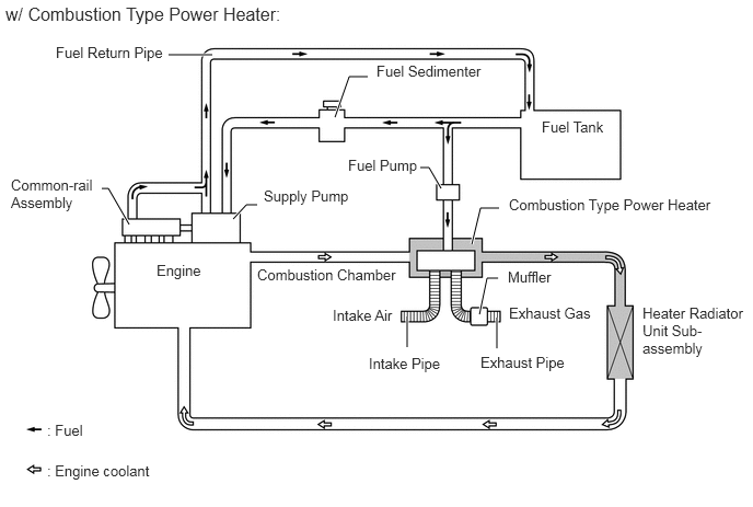
Combustion Type Power Heater
While the 1GD-FTV engines offer excellent combustion efficiency, they generate less heat. Therefore, depending on the operating condition, the water temperature remains low, making it difficult to ensure the proper heating effect. Thus, in order to provide adequate heating effect, a combustion type power heater is provided.
This heater system provides a combustion type power heater between the engine and the heater radiator unit sub-assembly. Air and fuel are introduced into the heater's combustion chamber, and a glow plug is used to ignite this mixture. By heating the engine coolant that flows around the combustion chamber, this system ensures the heating effect. The system can be activated or deactivated by turning on or off the power heater switch provided on the air conditioning control assembly.
PRECAUTION
Precaution for Refrigerant HFO-1234yf (R1234yf)
Compatibility
The parts used in the refrigerant cycle, the compressor oil, etc. of the HFO-1234yf (R1234yf) system are not compatible with the conventional HFC-134a (R134a) system.
Always use HFO-1234yf (R1234yf) as the refrigerant.
- CAUTION:
- ·
Do not charge the system with refrigerant near open flames, as HFO-1234yf (R1234yf) is combustible.
·When charging the system with refrigerant, make sure the area is well ventilated(especially be careful in areas where the gas can easily accumulate such as underlifts and in garage pits, as the gas is heavier than air).
·Follow any local regulations regarding combustible gases.
·Be sure to use a refrigerant recovery unit that is compatible with HFO-1234yf (R1234yf) systems.
- HINT:
-
The shape of the service port for refrigerant charging has an exclusive design conforming tointernational standards for HFO-1234yf (R1234yf) to prevent improper refrigerant charging.
Compressor Oil
Always use ND-OIL 12 as the compressor oil.
When parts of the air conditioning system are removed, quickly block off any areas that areexposed to the outside air with plugs, vinyl tape, etc., as the oil used for HFO-1234yf (R1234yf) systems absorbs moisture easily.
Do not allow the compressor oil to spray, as the oil used for HFO-1234yf (R1234yf) systemshas harmful effects on acrylic resins.