PARK ASSIST / MONITORING PARKING ASSIST MONITOR SYSTEM GENERAL/CONTROL/DETAILS DETAILS
FUNCTION OF MAIN COMPONENTS
| Component | Function |
|---|---|
|
*: Models with TOYOTA parking assist-sensor system |
|
| Rear Television Camera Assembly | ·
Captures images of the area behind the vehicle and outputs visual signals to the navigation receiver assembly. ·
The parking assist guide lines that are calculated based on signals from the steering sensor are superimposed on the captured image. Then, the image is sent to the navigation receiver assembly as video signals. ·
When the back door is open, superimposing of parking assist guide lines is canceled and only the captured image is sent as video signals. |
| Navigation Receiver Assembly | Displays images of the area behind the vehicle sent from the rear television camera assembly using the multi-display. |
| Multi-display | Receives visual signals composed of the area behind the vehicle with parking assist guide lines overlaid from the navigation receiver assembly, and displays them on the multi-display. |
| Skid Control ECU | Transmits received vehicle speed signals to the navigation receiver assembly. |
| Steering Angle Sensor | Detects the steering angle and transmits signals to the navigation receiver assembly. |
| Park/Neutral Position Switch Assembly | Transmits a signal telling the ECM that the shift lever is in R. |
| ECM | Sends received shift position signals to the navigation receiver assembly. |
| Clearance Warning ECU Assembly* | Sends TOYOTA parking assist-sensor system detection information to the navigation receiver assembly. |
| Main Body ECU (Driver Side Junction Block Assembly) | Outputs the back door courtesy switch signal to the navigation receiver assembly. |
OPERATING CONDITION
Parking assist monitor system operates when both of the following conditions are met:
The engine switch is on (IG).
The shift lever is in R.
FUNCTION
Area Displayed on Screen
Television Camera
Objects on the right of the vehicle appear on the right side of the multi-display, and objects on the left of the vehicle appear on the left side of the multi-display.
The rear television camera assembly uses a wide-angle lens. The perceived distance from images that appear on the screen differs from the actual distance.
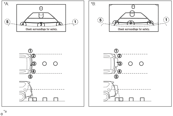
| *A | Models with Under Floor Mounted Spare Tire | *B | Models with Back Door Mounted Spare Tire |
| *a | The illustrations shown are examples only. The illustrations may differ from the actual vehicle screens. | - | - |
- HINT:
-
The area displayed on the screen may vary according to vehicle status or road conditions. The area covered by the rear television camera assembly is limited. The rear television camera assembly does not show objects close to either corner of the bumper or show the area under the bumper or the back door spare tire carrier*.
*: Models with back door mounted spare tire
CONSTRUCTION
Television Camera Assembly
The rear television camera assembly consists of a wide-angle lens and a Complementary Metal Oxide Semiconductor (CMOS).
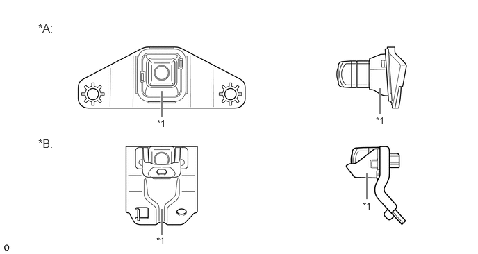
| *A | Models with Under Floor Mounted Spare Tire | *B | Models with Back Door Mounted Spare Tire |
| *1 | Rear Television Camera Assembly | - | - |
Multi-display (Parking Assist Monitor Display)
Perpendicular Parking Mode
Perpendicular parking mode consists of A: parking assist guide line display mode, B: course line deletion mode and C: estimated course line display mode. The initial (default) setting for perpendicular parking is estimated course line display mode.
When perpendicular parking mode is operating, fixed guide lines appear superimposed on a view of the area behind the vehicle. These guide lines can be used to assist the driver while backing up the vehicle.
Perpendicular parking mode can be set in the back camera guide line setting screen of the vehicle settings.
- HINT:
-
The illustrations shown are examples only. The illustrations may differ from the actual vehicle screens.
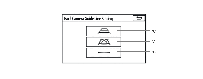
| *A | Parking Assist Guide Line Display Mode | *B | Distance Guide Line Display Mode |
| *C | Estimated Course Line Display Mode | - | - |
A description of the parking assist guide line display mode is provided in the following diagram:
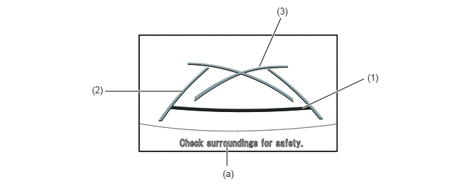
| Item | Outline | |
|---|---|---|
| (1) | Distance Guide Line (Red) | Indicates a position on the ground approximately 0.5 m (1.6 ft.) behind the rear bumper. |
| (2) | Vehicle Width Extension Guide Line (Blue) | Indicates the estimated vehicle width. |
| (3) | Parking Assist Guide Line (Blue) | Indicates the path the vehicle will follow if the driver turns the steering wheel fully. |
| (a) | Warning Message Display Area | Area where warning messages are displayed. |
A description of the distance guide line display mode is provided in the following diagram:
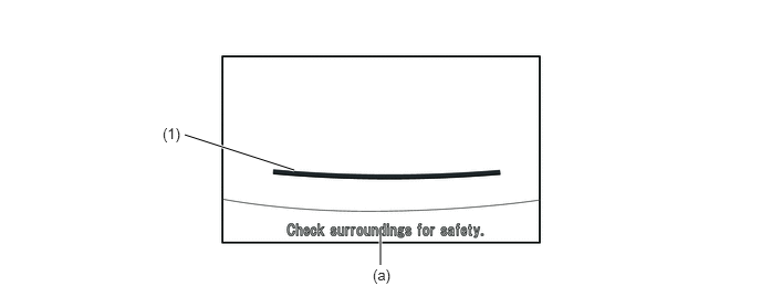
| Item | Outline | |
|---|---|---|
| (1) | Distance Guide Line (Red) | Indicates a position on the ground approximately 0.5 m (1.6 ft.) behind the rear bumper. |
| (a) | Warning Message Display Area | Area where warning messages are displayed. |
A description of the estimated course line display mode is provided in the following diagram.
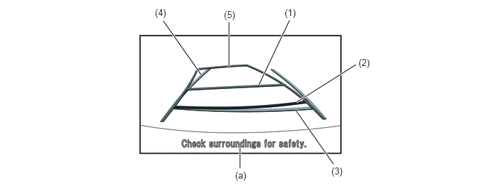
| Item | Outline | |
|---|---|---|
| (1) | Distance Guide Line (Yellow) | Moves together with estimated course lines in sync with the steering wheel. The center of the line indicates a position on the ground approximately 1.0 m (3.3 ft.) behind the rear bumper. |
| (2) | Distance Guide Line (Red) | Moves together with estimated course lines in sync with the steering wheel. The center of the line indicates a position on the ground approximately 0.5 m (1.6 ft.) behind the rear bumper. |
| (3) | Distance Guide Line (Blue) | Indicates a position on the ground approximately 0.5 m (1.6 ft.) behind the rear bumper. |
| (4) | Vehicle Width Extension Guide Line (Blue) | Indicates the estimated vehicle width. |
| (5) | Estimated Course Line (Yellow) | Moves in sync with the steering wheel to indicate the estimated reverse course of the vehicle. |
| (a) | Warning Message Display Area | Area where warning messages are displayed. |
OPERATION
Parking Assist Guide Line Display Mode (Perpendicular Parking) of Parking Assist Monitor System
To use parking assist guide line display mode in perpendicular parking when parking the vehicle in a parking space, perform the following procedure:
Select parking assist guide line display mode (Models without parallel assist parking assist mode)
Move the shift lever to R.
Select perpendicular parking mode. (Models with parallel assist parking assist mode)
Select parking assist guide line display mode. (Models with parallel assist parking assist mode)
An image appears on the display panel as illustrated below:
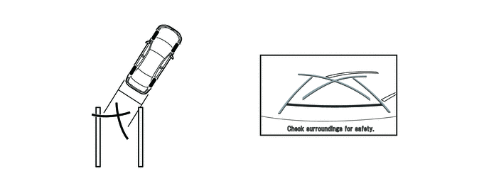
Back the vehicle up and stop at the position in which the parking assist guide line comes in contact with the left side of the intended parking position.
Turn the steering wheel fully to the right and back the vehicle up.
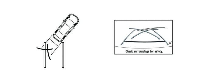
Continue backing the vehicle up until the vehicle is parallel to the plotted lines.
Once the vehicle is parallel, aim the steering wheel straight ahead and back the vehicle up to the target stop position.
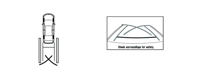
Estimated Course Line Display Mode (Perpendicular Parking) of Parking Assist Monitor System
To use estimated course line display mode in perpendicular parking when parking the vehicle in a parking space, perform the following procedure:
Select estimated course line display mode. (Models without parallel assist parking assist mode)
Move the shift lever to R.
Select perpendicular parking mode. (Models with parallel assist parking assist mode)
Select estimated course line display mode.
An image appears on the display panel as illustrated below:
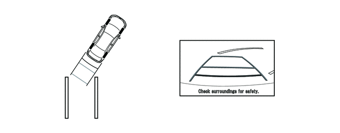
Turn the steering wheel so that the estimated course lines are within the parking space, and back up carefully.
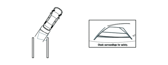
When the rear of the vehicle is within the parking space, turn the steering wheel in order to equalize the left and right intervals between the vehicle width extension lines and the parking space sidelines.
When the vehicle width extension guide lines and the parking space sidelines are parallel, straighten the steering wheel and then carefully back up until the entire vehicle is within the parking space.
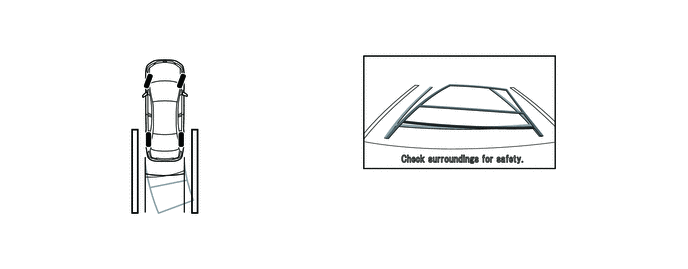
DIAGNOSIS
The parking assist monitor system is equipped with a diagnosis function which can display the diagnosis menus. The method for entering the diagnosis menu screen is the same as the method used for the multi-display. For details, refer to the Repair Manual.