NM27T0E
_57
Power Source / Network
_094214
1GD-FTV BATTERY / CHARGING
_0447123
CHARGING SYSTEM
DE
DETAILS
F
1GD-FTV BATTERY / CHARGING CHARGING SYSTEM DETAILS BATTERY SENSOR
CONSTRUCTION
a.
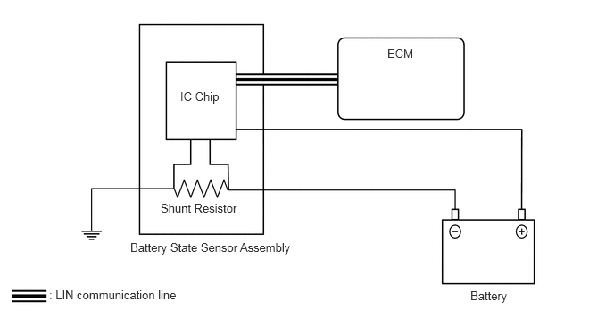
The battery state sensor assembly is installed to the negative (-) battery terminal and outputs the state of the battery based on the input/output current, voltage, temperature, SOC (State of Charge), SOH (State of Health), SOF (State of Function) and self-diagnosis results to the ECM via LIN communication.
b.
To detect the current, a shunt resistor installed inside the battery state sensor assembly is used to convert and calculate the voltage generated in the shunt resistor due to the battery charge and discharge current.
c.
The battery temperature is calculated from the resistance value of the thermistor built in the battery state sensor assembly.
0.573,3.354 2.625,3.594
2.052,0.24
10
false
: LIN communication line
2.104,1.042 2.594,1.292
0.49,0.25
10
false
IC Chip
4.521,0.542 5.396,1.01
0.875,0.469
10
false
ECM
5.49,3.365 6.292,3.635
0.802,0.271
10
false
Battery
1.521,2.802 3.531,3.104
2.01,0.302
10
false
Battery State Sensor Assembly
1.875,2.344 2.854,2.635
0.979,0.292
10
false
Shunt Resistor