RM27T0E
_51
Engine / Hybrid System
_053660
1GD-FTV ENGINE CONTROL
_0260468
INTAKE AIR TEMPERATURE SENSOR
G
1GD-FTV ENGINE CONTROL INTAKE AIR TEMPERATURE SENSOR INSPECTION
PROCEDURE

 89424D
1.INSPECT INTAKE AIR TEMPERATURE SENSOR
a.
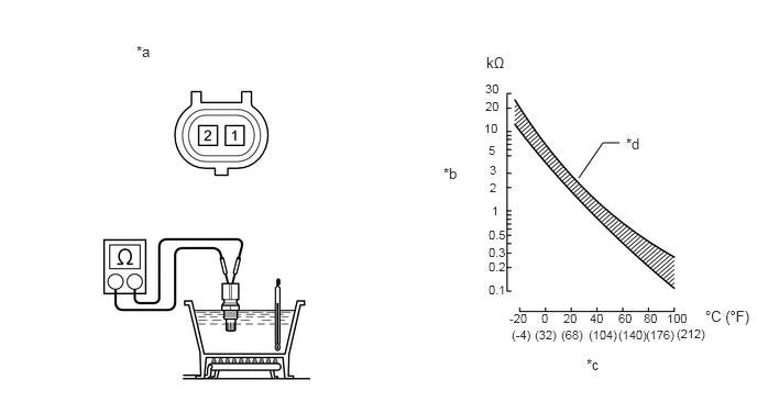
Measure the resistance according to the value(s) in the table below.
5.865,1.354 5.708,1.354
5.708,1.354 5.479,1.688
false
4.604,0.51 4.906,0.771
0.302,0.26
10
false
kΩ
4.594,0.771 4.917,0.979
0.323,0.208
8
false
30
4.594,0.938 4.917,1.146
0.323,0.208
8
false
20
4.583,1.146 4.906,1.354
0.323,0.208
8
false
10
4.625,1.354 4.948,1.563
0.323,0.208
8
false
5
4.635,1.542 4.958,1.75
0.323,0.208
8
false
3
4.635,1.708 4.958,1.917
0.323,0.208
8
false
2
4.656,1.927 4.979,2.135
0.323,0.208
8
false
1
4.625,2.458 4.948,2.667
0.323,0.208
8
false
0.2
4.625,2.323 4.948,2.531
0.323,0.208
8
false
0.3
4.625,2.156 4.948,2.365
0.323,0.208
8
false
0.5
4.625,2.677 4.948,2.885
0.323,0.208
8
false
0.1
5.125,2.948 5.302,3.135
0.177,0.188
8
false
0
5.333,2.948 5.531,3.115
0.198,0.167
8
false
20
5.583,2.948 5.792,3.125
0.208,0.177
8
false
40
5.854,2.948 6.052,3.135
0.198,0.188
8
false
60
6.094,2.948 6.313,3.135
0.219,0.188
8
false
80
6.313,2.948 6.583,3.125
0.271,0.177
8
false
100
4.823,2.948 5.052,3.115
0.229,0.167
8
false
-20
6.677,2.917 7.167,3.115
0.49,0.198
10
false
°C (°F)
4.844,3.104 5.073,3.281
0.229,0.177
8
false
(-4)
5.063,3.104 5.323,3.313
0.26,0.208
8
false
(32)
5.313,3.104 5.583,3.302
0.271,0.198
8
false
(68)
5.573,3.104 5.906,3.302
0.333,0.198
8
false
(104)
5.854,3.104 6.177,3.313
0.323,0.208
8
false
(140)
6.115,3.104 6.458,3.313
0.344,0.208
8
false
(176)
6.406,3.094 6.74,3.302
0.333,0.208
8
false
(212)
1.292,0.406 1.656,0.615
0.365,0.208
10
false
*a
4.198,1.563 4.563,1.771
0.365,0.208
10
false
*b
5.552,3.375 5.917,3.583
0.365,0.208
10
false
*c
5.927,1.281 6.292,1.49
0.365,0.208
10
false
*d
| *a | Component without harness connected
(Intake Air Temperature Sensor) |
*b | Resistance |
| *c | Temperature | *d | Acceptable Range |
- Standard Resistance:
Tester Connection Condition Specified Condition 1 - 2 20°C (68°F) 2.21 to 2.65 kΩ 60°C (140°F) 0.54 to 0.62 kΩ
- CAUTION:
- ·
Do not put your hands in the water warmed up during the inspection.
·Touching the hot water may result in burns.
- NOTICE:
-
When checking the intake air temperature sensor in water, do not allow water to contact the terminals. After completing the check, dry the intake air temperature sensor.
If the result is not as specified, replace the intake air temperature sensor.