Home › Engine / Hybrid System › 1KD-FTV (ENGINE MECHANICAL) › CYLINDER HEAD › 2015.06–2020.08
RM27T0E _51 Engine / Hybrid System _053664 1KD-FTV ENGINE MECHANICAL _0260517 CYLINDER HEAD A

1KD-FTV ENGINE MECHANICAL  CYLINDER HEAD  REASSEMBLY  


CAUTION / NOTICE / HINT

HINT:
·

Thoroughly clean all parts to be assembled.

·

Before installing the parts, apply fresh engine oil to all sliding and rotating surfaces.

·

Replace all gaskets and oil seals with new ones.


PROCEDURE

Hide 1.INSTALL STUD BOLT

HINT:

If a stud bolt is deformed or the threads are damaged, replace it.


a.

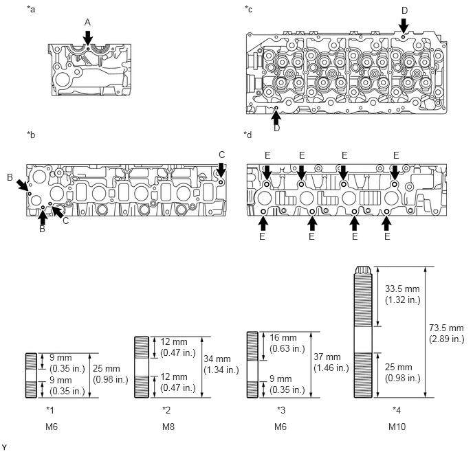
Install the stud bolts.

Torque:
for stud bolt A and D : 5.0 N*m (51 kgf*cm, 44 in.*lbf)
for stud bolt B : 7.0 N*m (71 kgf*cm, 62 in.*lbf)
for stud bolt C : 15 N*m (153 kgf*cm, 11 ft.*lbf)
for stud bolt E : 26 N*m (265 kgf*cm, 19 ft.*lbf)
A225490E01
0.406,0.052 0.604,0.229 0.198,0.177 10 false *a 3.708,0.052 3.906,0.229 0.198,0.177 10 false *c 0.406,1.958 0.604,2.135 0.198,0.177 10 false *b 3.688,1.958 3.885,2.135 0.198,0.177 10 false *d 0.75,5.333 1.344,5.719 0.594,0.385 10 false 9 mm (0.35 in.) 0.75,5.677 1.344,6.063 0.594,0.385 10 false 9 mm (0.35 in.) 0.698,6.135 0.917,6.313 0.219,0.177 10 false *1 2.458,6.135 2.677,6.313 0.219,0.177 10 false *2 0.948,3.26 1.094,3.438 0.146,0.177 10 false C 0.594,3.385 0.74,3.563 0.146,0.177 10 false B 3.313,2.26 3.458,2.438 0.146,0.177 10 false C 4.01,2.271 4.156,2.448 0.146,0.177 10 false E 4.531,2.271 4.677,2.448 0.146,0.177 10 false E 5.177,2.271 5.323,2.448 0.146,0.177 10 false E 5.958,2.271 6.104,2.448 0.146,0.177 10 false E 5.823,3.5 5.969,3.677 0.146,0.177 10 false E 5.333,3.5 5.479,3.677 0.146,0.177 10 false E 4.677,3.5 4.823,3.677 0.146,0.177 10 false E 3.927,3.5 4.073,3.677 0.146,0.177 10 false E 0.104,2.604 0.25,2.781 0.146,0.177 10 false B 1.281,0.25 1.427,0.427 0.146,0.177 10 false A 6.083,0.073 6.229,0.25 0.146,0.177 10 false D 4.146,1.854 4.292,2.031 0.146,0.177 10 false D 5.948,6.135 6.125,6.313 0.177,0.177 10 false *4 4.198,6.135 4.375,6.313 0.177,0.177 10 false *3 1.406,5.5 2,5.885 0.594,0.385 10 false 25 mm (0.98 in.) 2.427,5.094 3.021,5.479 0.594,0.385 10 false 12 mm (0.47 in.) 2.427,5.625 3.021,6.01 0.594,0.385 10 false 12 mm (0.47 in.) 3.083,5.354 3.677,5.74 0.594,0.385 10 false 34 mm (1.34 in.) 5.833,4.292 6.427,4.677 0.594,0.385 10 false 33.5 mm (1.32 in.) 5.833,5.479 6.427,5.865 0.594,0.385 10 false 25 mm (0.98 in.) 5.885,6.385 6.26,6.573 0.375,0.188 10 false M10 2.458,6.385 2.75,6.573 0.292,0.188 10 false M8 0.688,6.385 0.99,6.573 0.302,0.188 10 false M6 4.156,6.385 4.458,6.573 0.302,0.188 10 false M6 6.5,4.885 7.094,5.25 0.594,0.365 10 false 73.5 mm (2.89 in.) 4.083,5.031 4.677,5.417 0.594,0.385 10 false 16 mm (0.63 in.) 4.083,5.656 4.677,6.042 0.594,0.385 10 false 9 mm (0.35 in.) 4.75,5.323 5.344,5.708 0.594,0.385 10 false 37 mm (1.46 in.)

Text in Illustration
*1 Stud Bolt A and B *2 Stud Bolt C
*3 Stud Bolt D *4 Stud Bolt E
*a Front Side *b Intake Manifold Side
*c Cylinder Head Cover Side *d Exhaust Manifold Side


Hide 11117E 2.INSTALL NO. 1 STRAIGHT SCREW PLUG

HINT:

If the No. 1 straight screw plug is corroded, replace it.


a.

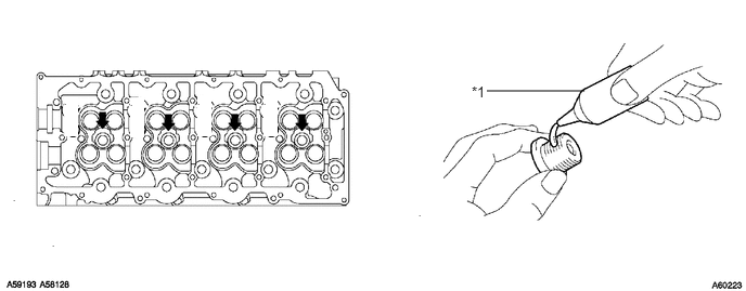
Apply adhesive to the end of each No. 1 straight screw plug.

Adhesive:

Toyota Genuine Adhesive 1324, Three Bond 1324 or equivalent


b.

Using a 6 mm hexagon wrench, install the No. 1 straight screw plugs.

Torque:
25 N*m (255 kgf*cm, 18 ft.*lbf)

U169064E01
5.615,0.875 4.677,0.875 false 4.531,0.802 4.688,0.969 0.156,0.167 10 false *1 0.5,2.292 0.698,2.427 0.198,0.135 6 false . 0.125,1.854 0.302,2.031 0.177,0.177 6 true . 4.021,2 4.198,2.177 0.177,0.177 6 true . 0.823,1.292 0.948,1.625 0.125,0.333 6 false . 1.25,0.938 1.385,1.323 0.135,0.385 6 true . 0.615,0.927 0.75,1.313 0.135,0.385 6 true . 1.896,0.927 2.031,1.313 0.135,0.385 6 true . 2.531,0.927 2.667,1.313 0.135,0.385 6 true .

Text in Illustration
*1 Adhesive - -


Hide 11183 3.INSTALL SEMICIRCULAR PLUG

a.

Remove any old seal packing (FIPG material).


b.

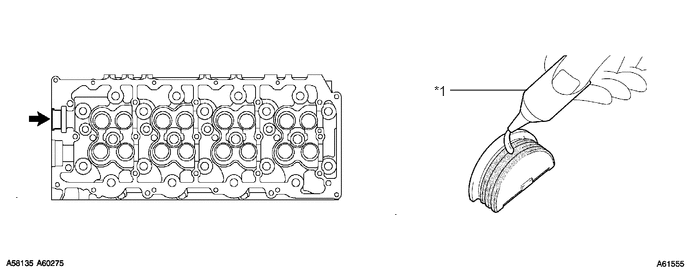
Apply seal packing to the semicircular plug as shown in the illustration.

Seal packing:

Toyota Genuine Seal Packing Black, Three Bond 1207B or equivalent


NOTICE:
·

The semicircular plug must be installed within 3 minutes after applying the seal packing.

·

Prevent seal packing from adhering to the camshaft thrust groove.


A061555E02
5.49,0.938 4.688,0.938 false 4.521,0.865 4.698,1.063 0.177,0.198 10 false *1 0.156,1.927 0.313,2.125 0.156,0.198 10 true . 4.104,2.104 4.26,2.302 0.156,0.198 10 true .

Text in Illustration
*1 Adhesive - -


c.

Install the semicircular plug to the cylinder head.


Hide 13711E 4.INSTALL INTAKE VALVE STEM OIL SEAL
a.
A059919E03
1.417,0.177 2.448,0.844 false 1.052,0.094 1.396,0.25 0.344,0.156 10 false SST

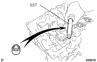
Using SST, push in a new oil seal.

SST
09201-41020  


Hide 13715A 5.INSTALL EXHAUST VALVE STEM OIL SEAL

a.

Using SST, push in a new oil seal.

SST
09201-41020  


Hide 13711 6.INSTALL INTAKE VALVE

a.
A058114E02
2.667,0.469 2.208,0.625 false 2.708,0.375 3.063,0.542 0.354,0.167 10 false SST

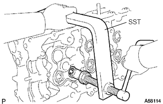
Install the valve, spring seat, compression spring and spring retainer.


b.

Using SST, compress the compression spring and install the 2 valve spring retainer locks to the valve stem.

SST
09202-70020  
09202-00021  


c.
A060277

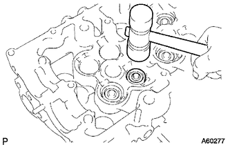
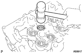
Using a plastic-faced hammer, lightly tap the valve stem tip to assure a proper fit.

NOTICE:

Be careful not to damage the valve stem tip.


Hide 13715 7.INSTALL EXHAUST VALVE

A058113E02
2.417,0.219 2.24,0.313 false 2.479,0.125 2.833,0.302 0.354,0.177 10 false SST

a.

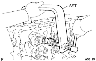
Install the valve, spring seat, compression spring and spring retainer.


b.

Using SST, compress the compression spring and install the 2 valve spring retainer locks to the valve stem.

SST
09202-70020  
09202-00021  


c.
A059917

Using a plastic-faced hammer, lightly tap the valve stem tip to assure a proper fit.

NOTICE:

Be careful not to damage the valve stem tip.