Home › Engine / Hybrid System › 1KD-FTV (ENGINE MECHANICAL) › CYLINDER BLOCK › 2015.06–2020.08
RM27T0E _51 Engine / Hybrid System _053664 1KD-FTV ENGINE MECHANICAL _0260518 CYLINDER BLOCK A

1KD-FTV ENGINE MECHANICAL  CYLINDER BLOCK  REPLACEMENT  


PROCEDURE

Hide 11431G 1.REPLACE TIGHT PLUG

NOTICE:

If water leaks from the tight plug or the plug is corroded, replace it.


a.

Remove the tight plugs.


b.

Apply adhesive to new tight plugs.

Adhesive:

Toyota Genuine Adhesive 1324, Three Bond 1324 or equivalent


NOTICE:

Do not start the engine for 1 hour after installation.


c.

Position A:

Using a 14 mm steel bar and hammer, tap in the tight plug as shown in the illustration.


d.

Other Positions:

Using SST and a hammer, tap in the tight plugs as shown in the illustration.

Position B

SST
09950-60010  (09951-00180)
09950-70010  (09951-07100)

Position C

SST
09950-60010  (09951-00190)
09950-70010  (09951-07100)

Position D

SST
09950-60010  (09951-00200)
09950-70010  (09951-07100)

Position E and H

SST
09950-60010  (09951-00350)
09950-70010  (09951-07100)

Position F

SST
09950-60010  (09951-00400, 09951-00450)
09950-70010  (09951-07100)

Position G

SST
09950-60010  (09951-00450)
09950-70010  (09951-07100)
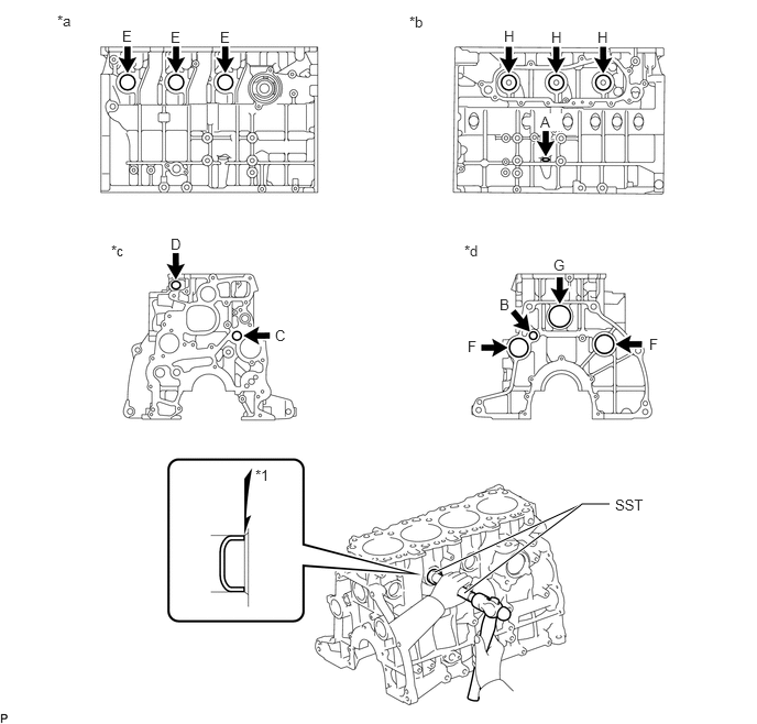
A447040E01
4.115,5.417 5.51,4.771 5.51,4.771 5.771,4.771 true 4.396,5.615 5.5,4.781 true 2.417,4.417 2.729,4.615 0.313,0.198 10 false *1 0.542,0.115 0.854,0.313 0.313,0.198 10 false *a 3.875,0.125 4.188,0.323 0.313,0.198 10 false *b 1.052,2.292 1.365,2.49 0.313,0.198 10 false *c 4.396,2.292 4.708,2.49 0.313,0.198 10 false *d 1.156,0.26 1.313,0.458 0.156,0.198 10 false E 1.615,0.271 1.771,0.469 0.156,0.198 10 false E 2.083,0.271 2.24,0.469 0.156,0.198 10 false E 4.771,0.26 4.927,0.458 0.156,0.198 10 false H 5.219,0.271 5.375,0.469 0.156,0.198 10 false H 5.656,0.271 5.813,0.469 0.156,0.198 10 false H 5.115,1.073 5.323,1.24 0.208,0.167 10 true A 1.615,2.229 1.771,2.427 0.156,0.198 10 false D 2.604,3.094 2.76,3.292 0.156,0.198 10 false C 4.427,3.198 4.583,3.396 0.156,0.198 10 false F 6.146,3.177 6.302,3.375 0.156,0.198 10 false F 4.729,2.802 4.885,3 0.156,0.198 10 false B 5.24,2.427 5.396,2.625 0.156,0.198 10 false G 5.823,4.698 6.281,4.896 0.458,0.198 10 false SST

Text in Illustration
*1 Stops - -
*a for Right Side *b for Left Side
*c for Front Side *d for Rear Side


Hide 2.REPLACE STRAIGHT PIN

NOTICE:

It is not necessary to remove the straight pin unless it is being replaced.


a.

Remove the straight pins.


b.

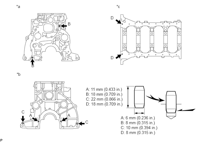
Using a plastic-faced hammer, tap in new straight pins to the cylinder block.

Standard Protrusion Height:
Item Specified Condition
Pin A 6 mm (0.234 in.) or less
Pin B 7.5 mm (0.295 in.) or less
Pin C 12 mm (0.472 in.) or less
Pin D 5 to 8 mm (0.197 to 0.315 in.) or less

A225495E01
0.552,0.135 0.76,0.302 0.208,0.167 10 false *a 3.938,0.135 4.156,0.302 0.219,0.167 10 false *c 2.292,0.729 2.479,0.917 0.188,0.188 10 false B 1.063,2.146 1.25,2.333 0.188,0.188 10 false B 4.083,3.917 5.396,4.615 1.313,0.698 10 false A: 6 mm (0.236 in.) B: 8 mm (0.315 in.) C: 10 mm (0.394 in.) D: 8 mm (0.315 in.) 2.906,2.948 4.229,3.688 1.323,0.74 10 false A: 11 mm (0.433 in.) B: 18 mm (0.709 in.) C: 22 mm (0.866 in.) D: 18 mm (0.709 in.) 0.563,2.438 0.771,2.615 0.208,0.177 10 false *b 0.729,3.719 0.885,3.875 0.156,0.156 10 false C 2.885,4.063 3.042,4.219 0.156,0.156 10 false C 3.74,1.875 3.896,2.031 0.156,0.156 10 false D 3.74,0.521 3.896,0.677 0.156,0.156 10 false D 0.99,3.833 1.146,3.99 0.156,0.156 10 true A 2.281,3.833 2.438,3.99 0.156,0.156 10 true A

Text in Illustration
*a for Front Side *b for Rear Side
*c for Oil Pan Side - -


Hide 3.REPLACE RING PIN

NOTICE:

It is not necessary to remove the ring pin unless it is being replaced.


a.

Remove the ring pins.


b.

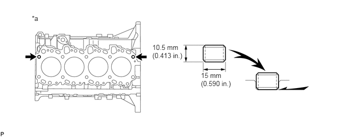
Using a plastic-faced hammer, tap in new ring pins to the cylinder block.

Standard Protrusion:

6 mm (0.236 in.) or less

A152219E03
0.65,0.289 0.864,0.497 0.214,0.208 10 *a 3.111,0.881 3.822,1.248 0.711,0.368 10 10.5 mm (0.413 in.) 4.103,1.46 4.789,1.827 0.685,0.368 10 15 mm (0.590 in.)

Text in Illustration
*a Cylinder Head Side - -